Nội dung toàn văn Circular No. 39/2010/TT-BGTVT National Technical Regulation on parts of road vehicles
|
MINISTRY
OF TRANSPORT |
SOCIALIST
REPUBLIC OF VIETNAM |
|
No. 39/2010/TT-BGTVT |
Hanoi, December 31, 2010 |
CIRCULAR
ON THE PROMULGATION OF 03 NATIONAL TECHNICAL REGULATION ON PARTS OF ROAD VEHICLES
Pursuant to the Law on Technical regulations and standards No. 68/2006/QH11 dated June 29, 2006 and the Government's Decree No. 127/2007/NĐ-CP dated August 01, 2007 detailing the implementation of a number of articles of the Law on Technical regulations and standards;
Pursuant to the Government's Decree No. 51/2008/NĐ-CP dated April 22, 2008, defining the functions, tasks, powers and organizational structure of the Ministry of Transport;
At the request of the Director of Science and Technology Department and the Director of the Vietnam Register,
Article 1. Promulgating together with this Circular 03 National Technical Regulation on parts of road vehicles:
1. National Technical Regulation on photometric characteristics of road vehicle headlamps.
Number: QCVN 35:2010/BGTVT.
2. National technical regulation on tires of motorcycles
Number QCVN 36:2010/BGTVT.
3. National technical regulation on engines of motorcycles
Number QCVN 37:2010/BGTVT.
Article 2. This Circular takes effect after 06 months from the day on which it is signed.
Article 3. The Chief of the Ministry Office, the Chief Ministerial Inspector, Directors of Departments, the Director of the Vietnam Register, heads of relevant organizations and individual concerned are responsible for the implementation of this Circular./.
|
|
THE
MINISTER |

SOCIALIST REPUBLIC OF VIETNAM
QCVN 35 : 2010/BGTVT
NATIONAL TECHNICAL REGULATION
PHOTOMETRIC CHARACTERISTICS OF ROAD VEHICLE HEADLAMPS
Hanoi - 2010
Foreword
QCVN 35:2010/BGTVT is compiled by the Vietnam Register, appraised by the Ministry of Science and Technology, and promulgated by the Ministry of Transport together with the Circular No. 39/2010/TT-BGTVT dated December 31, 2010.
This Regulation is complied based on TCVN 6955: 2001; TCVN 6902: 2001; TCVN 6974: 2001 promulgated together with the Decision No. 68/2001/QĐ-BKHCNMT dated December 28, 2012; TCVN 7223: 2002; TCVN 7224: 2002 promulgated together with the Decision No. 20/2002/QĐ-BKHCN dated December 21, 2002; TCVN 7344:2003; TCVN 7345: 2003; TCVN 7346: 2003 promulgated together with the Decision No. 38/2003/QĐ-BKHCN dated December 31, 2003 of the Minister of Natural Resources and Environment; ECE 112 and ECE 113.
NATIONAL TECHNICAL REGULATION ON PHOTOMETRIC CHARACTERISTICS OF ROAD VEHICLE HEADLAMPS
1. GENERAL PROVISIONS
1.1. Scope of regulation
This Circular is applicable to photometric characteristics of road vehicle headlamps (hereinafter referred to as headlamps).
1.2. Subjects of application
This Regulation is applicable to headlamp manufacturers, importers, road vehicle assemblers, importers, organizations and individuals related to the testing, inspection and certification of technical quality and safety of headlamps.
1.3. Definitions
1.3.1. Complete headlamp: means every part of a headlamp, including the reflector, lens, one or some electric light sources that are closed during the production process, and cannot be disassembled without damaging the headlamp.
1.3.2. Lens: the outermost component of the headlamp which transmits light through the illuminating surface
1.3.3. Coating: any product or products applied in one or more layers to the outer face of a lens.
1.3.4. Headlamps of different types: headlamps which differ in such essential respects as:
1.3.4.1. The trade name or mark;
1.3.4.2. The characteristics of the optical system;
1.3.4.3. The photometric characteristics; A change in the colour of the beam emitted by a headlamp of which other photometric characteristics are not changed does not constitute a change of headlamp type.
1.3.4.5. The kind of beam produced (passing beam, driving beam or both);
1.3.4.6. The materials constituting the lenses and coating (if any).
2. TECHNICAL PROVISIONS
2.1. Headlamps of motorcycles ≤ 50cc
Headlamps of motorcycles ≤ 50 cc are satisfactory when the requirements below are met:
2.1.1. Structural requirements
Structures of the headlamps must meet the requirements in Section 1 of one of the Appendices from 1 to 10.
2.1.2. Photometric characteristics
Photometric characteristics must meet the requirements in Section 2 of one of the Appendices from 1 to 10. The headlamps that are inspected in accordance with Section 2 of one of the Appendices from 1 to 7 must undergo the test on stability of their photometric characteristics during operation (Appendix 11)
2.1.3. Light color
The light color of the headlamps must satisfy the requirements in Section 3 of one of the Appendices from 1 to 10.
2.2. Headlamps of motorcycles > 50cc
Headlamps of motorcycles > 50cc are satisfactory when the requirements below are met:
2.2.1. Structural requirements
Structures of the headlamps must satisfy the requirements in Section 1 of one of the Appendices from 1 to 7.
2.2.2. Photometric characteristics
Photometric characteristics of the headlamps must satisfy the requirements in Section 2 of one of the Appendices from 1 to 7.
2.2.3. Light color
The light color of the headlamps must satisfy the requirements in Section 3 of one of the Appendices from 1 to 7.
2.2.4. Stability of photometric performance in operation
Stability of photometric performance in operation must conform to Appendix 11.
2.3. Headlamps of cars
Headlamps of cars are satisfactory when the requirements below are met:
2.3.1. Structural requirements
Structures of the headlamps must satisfy the requirements in Section 1 of one of the Appendices from 3 to 6.
2.3.2. Photometric characteristics
Photometric characteristics of the headlamps must satisfy the requirements in Section 2 of one of the Appendices from 3 to 6.
2.3.3. Light color
The light color of the headlamps must satisfy the requirements in Section 3 of one of the Appendices from 3 to 6.
2.3.4. Stability of photometric performance in operation
Stability of photometric performance in operation must satisfy Appendix 11.
Requirements for mass-produced headlamps
Mass-produced headlamps must satisfy the requirements in Appendix 12.
3. MANAGEMENT
3.1. Test methods
- The assembled and imported headlamps must be tested in accordance with the Decision No. 57/2007/QĐ-BGTVT the Decision No. 58/2007/QĐ-BGTVT dated November 21, 2007, the Decision no. 34/2005/QĐ-BGTVT the Decision No. 35/2005/QĐ-BGTVT dated July 21 2005 of the Minister of Transport on testing the quality, technical safety, and environmental safety of road vehicles.
- The headlamps produced at home or imported for type approval must be inspected and meet the requirements in Part 2 of Technical regulation.
3.2. Technical documents and samples
When testing, the manufacturers or importers of headlamps must provide the testing agency with technical documents and samples in accordance with Point 3.2.1 and 3.2.2 below.
3.2.1. Technical documents
Technical documents of headlamps must contain the information below:
- The headlamps are intended to provide passing beam, driving beam, or both;
- The headlamps are designed for left-hand traffic, right-hand traffic, or both;
- Nominal wattage of the lamp;
- Nominal voltage of the lamp;
- Voltage provided for the lamp when testing;
- The passing beam is whether symmetrical or asymmetrical;
- The headlamps are tested in Appendix 7 (A or B or C or D);
- The headlamps are tested in Appendix 6 (A or B);
- The detailed drawings to identify the types of headlamps.
3.2.2. Samples: 03 samples of a type of headlamp shall be tested for type approval, including:
- Testing the photometric characteristics and color of the light: 01 finished headlamp including the lens, reflector, and lamp;
- Testing the stability of photometric characteristics and color of the light: 02 finished headlamp including the lens, reflector, and lamp.
3.3. Testing report
The testing agency shall make a report on the test result that contains at least the information in this Regulation corresponding to each type of headlamps.
3.4. Application of regulation
Where the documents cited in this Regulation are amended or superseded, the new documents shall apply.
4. IMPLEMENTATION
4.1. Application dates
- The headlamps produced at home or imported for type approval shall apply this Regulation when it takes effect.
- The testing of photometric characteristics of motorcycles headlamps shall apply this Regulation when it takes effect.
- Testing photometric characteristics of car headlamps: the types of headlamps that are tested for the first time shall apply this Regulation after 02 years from the day on which it takes effect; the types of headlamps that already have the Certificates of Type approval shall apply this Regulation after 04 years from the day on which it takes effect.
- Testing the stability of photometric characteristics and light colors of motorcycle and car headlamps: apply this Regulation after 04 years from the day on which it takes effect.
4.2. Responsibilities of the Vietnam Register
The Vietnam Register shall organize and provide guidance on the implementation of this Regulation when testing the quality and technical safety of headlamps of road vehicles that are produced, assembled at home, or imported.
APPENDIX 1
TEST FOR PHOTOMETRIC CHARACTERISTICS OF MOTORCYCLE HEADLAMPS WITH A SYMMETRICAL PASSING BEAM
1. Structural requirements
1.1. Each sample must satisfy the requirements in this Section and Section 2.
1.2. The parts used for fixing the filament lamp and reflector must be made so that the lamp may be installed into place even the lamp is not seen.
1.3. The lens must be firmly fixed to the reflector to avoid movements during operation.
2. Photometric characteristics
2.1. Testing conditions
The testing system must meet the requirements in Appendix 15
2.1.1. A measuring screen (figure 1) shall be set up 25 m in front of the lamp and perpendicular to the line joining the filament and point HV.
2.1.2. The screen illumination values mentioned in Point 2.2 and 2.3 must be measured by a photoreceptor, the effective area of which shall be contained within a square of 65 mm side
2.1.3. Test voltage
Specified by technical documents of the lamp.
2.1.4. The headlamp shall be so aimed that:
2.1.4.1. Laterally, the beam is symmetrical with reference to the line V-V (figure 1).
2.1.4.2. Vertically, the headlamp shall be so aimed that the “cut-off” line of the passing beam is situated 250 mm below h-h line (figure 1).
2.2. Requirements for passing beam
2.2.1. The passing beam must produce a sufficiently sharp “cut-off” line to identify its position on the measuring screen. The “cut-off” line must be a horizontal straight line over at least 50 or 2187 mm to both sides of the line V-v (figure 1).
2.2.2. The illumination produced by the passing beam on the screens shall meet the following requirements:
Table 1. Required illumination of measuring points
|
No. |
Test points |
Required illumination (lux) |
|
1 |
Any point on and above h-h line |
≤ 0.7 |
|
2 |
Any point on line 50L-50R except 50V (1) |
≥1.5 |
|
3 |
Point 50V |
≥ 3 |
|
4 |
Any point on line 25L-25R |
≥ 3 |
|
5 |
Any point in zone IV |
≥ 1.5 |
(1) Intensity 50R/50V ≥ 0.25
2.3. Requirements for driving beam
2.3.1. The point with the maximum illumination of the driving beam shall be situated not more than 0.60 or 262mm above or below the line h-h (figure 1).
2.3.2. The maximum value (Emax) of illumination of the driving beam shall be at least 32 lux.
2.3.3. The illumination produced by the driving beam on the screens shall meet the following requirements:
2.3.3.1. The illumination of the intersection HV of lines h-h and v-v shall reach at least 90% of maximum illumination;
2.3.3.2. Starting from point HV, horizontally to the right and left, the illumination of the driving beam shall be not less than 12 lux up to a distance of 1125 mm and not less than 3 lux up to a distance of 2250 mm.
3. Color of the light
The colour of the light emitted shall be white and selective yellow. Expressed in CIE trichromatic coordinates, the light of the beams shall be within the following boundaries
Limit towards red y ≥ 0.138 + 0.58 x
Limit towards green y ≤ 1.29 + 0.1 x
Limit towards white y ≥ -x + 0.966
Limit towards the spectrum locus y ≤ -x + 0.992
4. Measuring screen

Figure 1: Measuring screen.
Notes:
*/ Dimensions are expressed as degrees when measuring in accordance with Principle 2 of Appendix 15, and in length when measuring in accordance with Principle 1 of Appendix 15.
These notes are applicable to the remaining cases.
APPENDIX 2
TEST FOR PHOTOMETRIC CHARACTERISTICS OF MOTORCYCLE HEADLAMPS WITH AN ASYMMETRICAL PASSING BEAM
1. Structural requirements
1.1. Each sample must satisfy the requirements in this Section and Section 2.
1.2. The parts used for fixing the filament lamp and reflector must be made so that the filament lamp may be installed into place even the lamp is not seen.
1.3. The lens must be firmly fixed to the reflector to avoid movements during operation.
2. Photometric characteristics
2.1. Testing conditions
The testing system must meet the requirements in Appendix 15
2.1.1. A measuring screen (figure 1) shall be set up 25 m in front of the lamp and perpendicular to the line joining the filament and point HV.
2.1.2. The screen illumination values mentioned in Point 2.2.2 and 2.3 must be measured by a photoreceptor, the effective area of which shall be contained within a square of 65 mm side
2.1.3. Test voltage
Specified by technical documents of the lamp.
2.1.4. The headlamp shall be so aimed that:
2.1.4.1. The “cut-off” line of the passing beam on the left-half of the measuring screen is horizontal;
2.1.4.2. The horizontal part of the “cut-off” line of the passing beam is situated on the screen 250 mm below h-h line (figure 1).
2.1.4.1. The “elbow” of the "cut-off” line of the passing beam is on V-V line (figure 1).
If the passing beam does not have a “cut-off” with a clear “elbow”, the adjustment shall be effected in the manner which best satisfies the requirements for illumination at points 75 R and 50 R;
2.1.4.4. Where a headlamp so aimed does not meet the requirements in Point 2.2.2 and 2.3, the alignment may be changed, provided the axis of the beam is not displaced by more than 10 or 436 mm to the left or right. The horizontal part of the “cut-off” line of the passing beam must not extend beyond h-h line (figure 1).
2.2. Requirements for passing beam
2.2.1. By observation, the passing beam must produce a sufficiently sharp “cut-off” line to identify its position on the measuring screen. The "cut-off" must be a horizontal straight line on the left; on the right side, it must not extend beyond the broken line HV H1 H4 formed by a straight line HV H1 making an angle of 450 with the horizontal and the straight line H1 H4, 250 mm above the straight line h-h, or the straight line HV H3, inclined at an angle of 150 with the horizontal (figure 1).
2.2.2. The illumination produced by the passing beam on the screens shall meet the following requirements:
Table 1. Required illumination of measuring points
|
No. |
Point on measuring screen |
Required illumination (lux) |
|
1 |
B50L |
≤ 0.3 |
|
2 |
75R |
≥ 6 |
|
3 |
50R |
≥ 6 |
|
4 |
25L |
≥ 1.5 |
|
5 |
25R |
≥ 1.5 |
|
6 |
Any point in zone III |
≤ 0.7 |
|
7 |
Any point in zone IV |
≥ 2 |
|
8 |
Any point in zone I |
≤ 20 |
2.3. Requirements for driving beam
2.3.1. The illumination produced by the driving beam on the screens shall meet the following requirements:
2.3.3.1. The illumination of the intersection HV of h-h and v-v shall reach at least 90% of maximum illumination; That maximum illumination (Emax) shall not be less than 32 lux and not exceed 240 lux;
2.3.1.2. Starting from point HV, horizontally to the right and left, the illumination of the driving beam shall be not less than 16 lux up to a distance of 1125 mm and not less than 4 lux up to a distance of 2250 mm.
3. Color of the light
The colour of the light emitted shall be white and selective yellow. Expressed in CIE trichromatic coordinates, the light of the beams shall be within the following boundaries:
Limit towards red y ≥ 0.138 + 0.58 x
Limit towards green y ≤ 1.29 x - 0.1
Limit towards white y ≥ -x + 0.966
Limit towards the spectrum locus y ≤ -x +0.992
4. Measuring screen
Figure 1: Measuring screen.
APPENDIX 3
TEST FOR PHOTOMETRIC CHARACTERISTICS OF ROAD VEHICLE HEADLAMPS EMITTING AN ASYMMETRICAL PASSING BEAM OR A DRIVING BEAM OR BOTH USING 13 POINTS AND 3 ZONES
1. Structural requirements
1.1. Each sample must satisfy the requirements in this Section and Section 2.
1.2. The parts used for fixing the filament lamp and reflector must be made so that the lamp may be installed into place even the lamp is not seen.
1.3. The lens must be firmly fixed to the reflector to avoid movements during operation.
2. Photometric characteristics
2.1. Testing conditions
The testing system must meet the requirements in Appendix 15
2.1.1. A measuring screen (figure 1) shall be set up 25 m in front of the lamp and perpendicular to the line joining the filament and point HV.
2.1.2. The screen illumination values mentioned in Point 2.2.2 and 2.3 must be measured by a photoreceptor, the effective area of which shall be contained within a square of 65 mm side
2.1.3. Test voltage
Specified by technical documents of the lamp.
2.1.4. The headlamp shall be so aimed that:
2.1.4.1. The “cut-off” line of the passing beam on the left-half of the measuring screen is horizontal;
2.1.4.2. The horizontal part of the “cut-off” line of the passing beam is situated on the screen 250 mm below h-h line (figure 1).
2.1.4.3. Where a headlamp so aimed does not meet the requirements in Point 2.2.2 and 2.3, the alignment may be changed, provided the axis of the beam is not displaced by more than 10 or 436 mm to the left or right. The horizontal part of the “cut-off” line of the passing beam must not extend beyond h-h line (figure 1).
2.2. Requirements for passing beam
2.2.1. By observation, the passing beam must produce a sufficiently sharp “cut-off” line to identify its position on the measuring screen. The "cut-off" must be a horizontal straight line on the left; on the right side, it must be horizontal or within 150 from the horizontal line (figure 1).
2.2.2. The illumination produced by the passing beam on the screens shall meet the following requirements:
Table 1. Required illumination of measuring points
|
No. |
Point on measuring screen |
Required illumination (lux) |
|
1 |
B50L |
≤ 0.4 |
|
2 |
75R |
≥ 6 |
|
3 |
50R |
≥ 6 |
|
4 |
25L |
≥ 1.5 |
|
5 |
25R |
≥ 1.5 |
|
6 |
Any point in zone III |
≤ 0.7 |
|
7 |
Any point in zone IV |
≥ 2 |
|
8 |
Any point in zone I |
≤ 20 |
|
9 |
”1”+”2”+”3” |
≥ 0.3 |
|
10 |
”4”+”5”+”6” |
≥ 0.6 |
|
11 |
”7” |
≥ 0.1 and ≤ 0.7 |
|
12 |
”8” |
≥ 0.2 and ≤ 0.7 |
2.3. Requirements for driving beam
2.3.1. The illumination produced by the driving beam on the screens shall meet the following requirements:
2.3.3.1. The illumination of the intersection HV of h-h and v-v lines shall reach at least 90% of maximum illumination; This maximum illumination must not fall below 32 lux;
2.3.1.2. Starting from point HV, horizontally to the right and left, the illumination of the driving beam shall be not less than 16 lux up to a distance of 1125 mm and not less than 4 lux up to a distance of 2250 mm.
3. Color of the light
The colour of the light emitted shall be white and selective yellow. Expressed in CIE trichromatic coordinates, the light of the beams shall be within the following boundaries:
Limit towards red y ≥ 0.138 + 0.58 x
Limit towards green y ≤ 1.29 x - 0.1
Limit towards white y ≥ -x + 0.966
Limit towards the spectrum locus y ≤ -x +0.992
4. Measuring screen
Figure 1: Measuring screen.
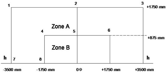
Figure 2: Measuring points from 1 to 8.
APPENDIX 4
TEST FOR PHOTOMETRIC CHARACTERISTICS OF COMPLETE HEADLAMPS EMITTING AN ASYMMETRICAL PASSING BEAM OR A DRIVING BEAM OR BOTH
1. Structural requirements
1.1. Each sample must satisfy the requirements in this Section and Section 2.
1.2. The electrodes connected to the filament must be firmly fixed to the lamp.
2. Photometric characteristics
2.1. Testing conditions
The testing system must meet the requirements in Appendix 15
2.1.1. A measuring screen (figure 1) shall be set up 25 m in front of the lamp and perpendicular to the line joining the filament and point HV.
2.1.2. The screen illumination values mentioned in Point 2.2.2 and 2.3 must be measured by a photoreceptor, the effective area of which shall be contained within a square of 65 mm side.
2.1.3. Test voltage
Specified by technical documents of the lamp.
2.1.4. The complete lamp shall be so aimed that:
2.1.4.1. The “cut-off” line of the passing beam on the left-half of the measuring screen is horizontal;
2.1.4.2. The horizontal part of the “cut-off” line of the passing beam is situated on the screen 250 mm below h-h line (figure 1).
2.1.4.3. Where a headlamp so aimed does not meet the requirements in Point 2.2.2 and 2.3, the alignment may be changed, provided the axis of the beam is not displaced by more than 10 or 436 mm to the left or right. The horizontal part of the “cut-off” line of the passing beam must not extend beyond h-h line (figure 1).
2.2. Requirements for passing beam
2.2.1. By observation, the passing beam must produce a sufficiently sharp “cut-off” line to identify its position on the measuring screen. The "cut-off" must be a horizontal straight line on the left; on the right side, it must be horizontal or within 150 on a horizontal plane (figure 1).
2.2.2. The illumination produced by the passing beam on the screens shall meet the following requirements:
Table 1. Required illumination of measuring points
|
No. |
Point on measuring screen |
Required illumination (lux) |
|
1 |
B50L |
≤ 0.3 |
|
2 |
75R |
≥ 6 |
|
3 |
50R |
≥ 6 |
|
4 |
25L |
≥ 1.5 |
|
5 |
25R |
≥ 1.5 |
|
6 |
Any point in zone III |
≤ 0.7 |
|
7 |
Any point in zone IV |
≥ 2 |
|
8 |
Any point in zone I |
≤ 20 |
2.3. Requirements for driving beam
2.3.1. The illumination produced by the driving beam on the screens shall meet the following requirements:
2.3.3.1. The illumination of the intersection HV of h-h and v-v lines shall reach at least 90% of maximum illumination; This maximum illumination must not fall below 32 lux;
2.3.1.2. Starting from point HV, horizontally to the right and left, the illumination of the driving beam shall be not less than 16 lux up to a distance of 1125 mm and not less than 4 lux up to a distance of 2250 mm.
3. Color of the light
The colour of the light emitted shall be white and selective yellow. Expressed in CIE trichromatic coordinates, the light of the beams shall be within the following boundaries:
Limit towards red y ≥ 0.138 + 0.58 x
Limit towards green y ≤ 1.29 x - 0.1
Limit towards white y ≥ -x + 0.966
Limit towards the spectrum locus y ≤ -x +0.992
4. Measuring screen
Figure 1: Measuring screen.
APPENDIX 5
TESTING PHOTOMETRIC CHARACTERISTICS OF ROAD VEHICLE HEADLAMPS EMITTING AN ASYMMETRICAL PASSING BEAM OR A DRIVING BEAM OR BOTH USING 18 POINTS AND 3 ZONES
1. Structural requirements
1.1. Each sample must satisfy the requirements in this Section and Section 2.
1.2. The parts used for fixing the filament lamp and reflector must be made so that the filament lamp may be installed into place even the lamp is not seen.
1.3. The lens must be firmly fixed to the reflector to avoid movements during operation.
2. Photometric characteristics
2.1. Testing conditions
The testing system must meet the requirements in Appendix 15
2.1.1. A measuring screen (figure 1) shall be set up 25 m in front of the lamp and perpendicular to the line joining the filament and point HV.
2.1.2. The screen illumination values mentioned in Point 2.2.2 and 2.3 must be measured by a photoreceptor, the effective area of which shall be contained within a square of 65 mm side
2.1.3. Test voltage
Specified by technical documents of the lamp.
2.1.4. The headlamp shall be so aimed that:
2.1.4.1. The “cut-off” line of the passing beam on the left-half of the measuring screen is horizontal;
2.1.4.2. The horizontal part of the “cut-off” line of the passing beam is situated on the screen 250 mm below h-h line (figure 1).
2.1.4.1. The “elbow” of the "cut-off” line of the passing beam is on V-V line (figure 1).
If the passing beam does not have a “cut-off” with a clear “elbow”, the adjustment shall be effected in the manner which best satisfies the requirements for illumination at points 75 R and 50 R;
2.1.4.4. Where a headlamp so aimed does not meet the requirements in Point 2.2.2 and 2.3, the alignment may be changed, provided the axis of the beam is not displaced by more than 10 or 436 mm to the left or right. The horizontal part of the “cut-off” line of the passing beam must not extend beyond h-h line (figure 1).
2.2. Requirements for passing beam
2.2.1. By observation, the passing beam must produce a sufficiently sharp “cut-off” line to identify its position on the measuring screen. The "cut-off" must be a horizontal straight line on the left; on the right side, it must not extend beyond the broken line HV H1 H4 formed by a straight line HV H1 making an angle of 450 with the horizontal and the straight line H1 H4, 250 mm above the straight line h-h, or the straight line HV H3, inclined at an angle of 150 with the horizontal (figure 1).
2.2.2. The illumination produced by the passing beam on the screens shall meet the following requirements:
Table 1. Required illumination of measuring points
|
No. |
Point on measuring screen |
Required illumination (lux) |
|
1 |
B50L |
≤ 0.4 |
|
2 |
75R |
≥ 12 |
|
3 |
75L |
≤ 12 |
|
4 |
50L |
≤ 15 |
|
5 |
50R |
≥ 12 |
|
6 |
50V |
≥ 6 |
|
7 |
25L |
≥ 2 |
|
8 |
25R |
≥ 2 |
|
9 |
Any point in zone III |
≤ 0.7 |
|
10 |
Any point in zone IV |
≥ 3 |
|
11 |
Any point in zone I |
≤ 2x(E50R) |
|
12 |
”1”+”2”+”3” |
≥ 0.3 |
|
13 |
”4”+”5”+”6” |
≥ 0.6 |
|
14 |
”7” |
≥ 0.1 and ≤ 0.7 |
|
15 |
”8” |
≥ 0.2 and ≤ 0.7 |
E50R is the value of illumination at point 50R
2.3. Requirements for driving beam
2.3.1. The illumination produced by the driving beam on the screens shall meet the following requirements:
2.3.3.1. The illumination of the intersection HV of lines h-h and v-v shall reach at least 80% of maximum illumination; That maximum illumination (Emax) shall not be less than 48. This maximum illumination must exceed 240 lux. In case a passing headlamp and driving headlamp are combined to give a driving beam, this maximum value shall not be more than 16 times the illumination measured for the passing beam at point 75R.
2.3.1.2. Starting from point HV, horizontally to the right and left, the illumination of the driving beam shall be not less than 24 lux up to a distance of 1125 mm and not less than 6 lux up to a distance of 2250 mm.
3. Color of the light
The colour of the light emitted shall be white and selective yellow. Expressed in CIE trichromatic coordinates, the light of the beams shall be within the following boundaries:
Limit towards red y ≥ 0.138 + 0.58 x
Limit towards green y ≤ 1.29 x - 0.1
Limit towards white y ≥ -x + 0.966
Limit towards the spectrum locus y ≤ -x +0.992
4. Measuring screen
Figure 1: Measuring screen.
Figure 2: Measuring points from 1 to 8.
APPENDIX 6
TEST FOR PHOTOMETRIC CHARACTERISTICS OF CLASS A AND B HEADLAMPS THAT EMIT AN ASYMMETRICAL PASSING BEAM OR A DRIVING BEAM OR BOTH
1. Structural requirements
1.1. Each sample must satisfy the requirements in this Section and Section 2.
1.2. The parts used for fixing the filament lamp and reflector must be made so that the filament lamp may be installed into place even the lamp is not seen.
1.3. The lens must be firmly fixed to the reflector to avoid movements during operation.
2. Photometric characteristics
2.1. Testing conditions
The testing system must meet the requirements in Appendix 15
2.1.1. A measuring screen (figure 1) shall be set up 25 m from the lamp and perpendicular to the line joining the filament and point HV.
2.1.2. The screen illumination values mentioned in Point 2.2.2 and 2.3 must be measured by a photoreceptor, the effective area of which shall be contained within a square of 65 mm side.
2.1.3. Test voltage
Specified by technical documents of the lamp.
2.1.4. The headlamp shall be so aimed that:
2.1.4.1. The “cut-off” line of the passing beam on the left-half of the measuring screen is horizontal.
2.1.4.2. The horizontal part of the “cut-off” line of the passing beam is situated 250 mm below h-h line (figure 1).
2.1.4.1. The “elbow” of the "cut-off” line of the passing beam is on v-v line (figure 1).
2.1.3.4. Where a headlamp so aimed does not meet the requirements in Point 2.2.2 and 2.3, the alignment may be changed, provided the axis of the beam is not displaced by more than 10 or 436 mm to the left or right. The horizontal part of the “cut-off” line of the passing beam must not extend beyond h-h line (figure 1).
2.2. Requirements for passing beam
2.2. By observation, the passing beam must produce a sufficiently sharp “cut-off” line to identify its position on the measuring screen. The "cut-off" must be a horizontal straight line on the left; on the right side, it must not extend beyond the broken line HV H1 H4 formed by a straight line HV H1 making an angle of 450 with the horizontal and the straight line H1 H4, 250 mm above the straight line h-h, or the straight line HV H3, inclined at an angle of 150 with the horizontal (figure 1).
13. In case the “cut-off” is not able to be determined visually, it shall be determined instrumentally according to Appendix 13 to this Regulation.
2.2.2. The illumination produced by the passing beam on the screens shall meet the following requirements:
Table 1. Required illumination of measuring points
|
No. |
Point on measuring screen |
Required illumination (lux) |
|
|
Class A |
Class B |
||
|
1 |
B50L |
≤ 0.4 |
≤ 0.4 |
|
2 |
75R |
≥ 6 |
≥ 12 |
|
3 |
75L |
≤ 12 |
≤ 12 |
|
4 |
50L |
≤ 15 |
≤ 15 |
|
5 |
50R |
≥ 6 |
≥ 12 |
|
6 |
50V |
- |
≥ 6 |
|
7 |
25L |
≥ 1.5 |
≥ 2 |
|
8 |
25R |
≥1.5 |
≥2 |
|
9 |
Any point in zone III |
≤ 0.7 |
≤ 0.7 |
|
10 |
Any point in zone IV |
≥ 2 |
≥ 3 |
|
11 |
Any point in zone I |
≤ 20 |
≤ 2.(E50R) |
|
12 |
”1”+”2”+”3” |
≥ 0.3 |
≥ 0.3 |
|
13 |
”4”+”5”+”6” |
≥ 0.6 |
≥ 0.6 |
|
14 |
”7” |
≥ 0.1 and ≤ 0.7 |
≥ 0.1 and ≤ 0.7 |
|
15 |
”8” |
≥ 0.2 and ≤ 0.7 |
≥ 0.2 and ≤ 0.7 |
E50R is the value of illumination at point 50R
2.3. Requirements for driving beam
2.3.1. The illumination produced by the driving beam on the screens shall meet the following requirements:
2.3.3.1. The illumination of the intersection HV of lines h-h and v-v shall reach at least 80% of maximum illumination; That maximum illumination (EM) shall not be less than 32 lux for Class A headlamps and 48 lux for Class B headlamps. The maximum value shall not exceed 240 lux. In case a passing headlamp and driving headlamp are combined to give a driving beam, this maximum value shall not be more than 16 times the illumination measured for the passing beam at point 75R.
2.3.3.2. Starting from point HV, horizontally to the right and left, the illumination of the driving beam shall be not less than 16 lux for Class A headlamps and 24 lux for Class B headlamps up to a distance of 1125 mm; and not less than 4 lux for Class A headlamps and 6 lux for Class B headlamps up to a distance of 2250 mm.
3. Light color
The colour of the light emitted shall be white. Expressed in CIE trichromatic coordinates, the light of the beams shall be within the following boundaries:
Limit towards blue x ≥ 0.310
Limit towards yellow x ≤ 0.500
Limit towards green y ≤ 0.150 + 0.640 x
Limit towards green y ≤ 0.440
Limit towards purple y ≥ 0.050 +0.750 x
Limit towards red y ≥ 0.382
4. Measuring screen
Figure 1: Measuring screen.
Figure 2: Measuring points from 1 to 8.
APPENDIX 7
TEST FOR PHOTOMETRIC CHARACTERISTICS OF HEADLAMPS EMITTING SYMMETRICAL PASSING BEAM OR DRIVING BEAM OR BOTH
1. Structural requirements
1.1. Each sample must satisfy the requirements in this Section and Section 2.
1.2. The parts used for fixing the filament lamp and reflector must be made so that the filament lamp may be installed into place even the lamp is not seen.
1.3. The lens must be firmly fixed to the reflector to avoid movements during operation.
2. Photometric characteristics
2.1. Testing conditions
The testing system must meet the requirements in Appendix 15
2.1.1. A measuring screen (figure 1, 2, 3) shall be set up 25 m in front of the lamp and perpendicular to the line joining the filament and point HV.
2.1.2. The screen illumination values mentioned in Point 2.2.3 and 2.3 must be measured by a photoreceptor, the effective area of which shall be contained within a square of 65 mm side
2.1.3. Test voltage
Specified by technical documents of the lamp.
2.1.4. The headlamp shall be so aimed that:
2.1.4.1. The passing beam is symmetrical to the line V-V;
2.1.4.2. The horizontal “cut-off” line of the passing beam is situated 250 mm below H-H line (figure 1, 2, 3).
2.2. Requirements for passing beam
2.2.1. By observation, the passing beam must produce a sufficiently sharp “cut-off” line to identify its position on the measuring screen. The "cut-off" line must be substantially horizontal over a an extent of at least ± 30 or ± 1310 mm for Class A, C and D headlamps, and at least ± 50 or ± 2187 mm for Class B headlamps.
In case the “cut-off” line is not be able to determined visually, it shall be determined instrumentally according to Appendix 14 to this Regulation.
2.2.2. Where a headlamp so aimed does not meet the requirements in Point 2.2.3 and 2.3, the alignment may be changed, provided the axis of the beam is not displaced by more than 10 or 436 mm to the left or right. The horizontal part of the “cut-off” line of the passing beam must not extend beyond H-H line (figure 1, 2, 3).
2.2.3. The illumination produced by the passing beam on the screens shall meet the following requirements:
2.2.3.1. Requirements for Class A headlamps:
Table 1. Required illumination of measuring points
|
Any point above line H-H |
≤ 0.32 lux |
|
Any point on line 25L-25R |
³ 1.28 lux |
|
Any point on line 12.5L-12.5R |
³ 0.64 lux |
2.2.3.2. Requirements for Class B headlamps:
Table 2. Required illumination of measuring points
|
Any point above line H-H |
≤ 0.7 lux |
|
Any point on line 50L-50R except 50V |
³ 1.5 lux |
|
Point 50V |
³ 3 lux |
|
Any point on line 25L-25R |
³ 3 lux |
|
Any point in zone IV |
³ 1.5 lux |
Ratio of intensity 50R/50V ³ 0.25.
2.2.3.3. Requirements for Class C and Class D headlamps:
Table 3. Required illumination of the points/lines/zones on the measuring screen
|
Test point/line/zone |
Position in B-beta Grid in angular degrees Vertical beta Horizontal B |
Required illumination (lux) at 25 m |
||||
|
Min |
Max |
|||||
|
Class D |
Class C |
Class D |
Class C |
|||
|
>125cc |
≤125cc |
>125cc |
≤125cc |
|||
|
1 |
0.86 D |
3.5 R |
2.3 |
15.4 |
||
|
2 |
0.86 D |
0 |
5.8 |
2.9 |
- |
|
|
3 |
0.86 D |
3.5 L |
2.3 |
15.4 |
||
|
4 |
0.50 U |
1.50L&1.50R |
- |
1.08 |
||
|
6 |
2.00 D |
15L & 15R |
1.28 |
0.64 |
- |
|
|
7 |
4.00 D |
20L & 20R |
0.38 |
0.19 |
- |
|
|
8 |
0 |
0 |
- |
1.92 |
||
|
Line 11 |
2.00 D |
9L to 9R |
1.6 |
- |
||
|
Line 12 |
7.00 U |
10L to 10R |
- |
0.3; but 0.96 if within 2 degrees cone |
||
|
Line 13 |
10.00 U |
10L to 10R |
- |
0.15; but 0.64 if within 2 degrees cone |
||
|
Line 14 |
10U to 90U |
0 |
- |
0.15; but 0.64 if within 2 degrees cone |
||
|
15 |
4.00U |
8.0L |
0.1 |
1.08 |
||
|
16 |
4.00U |
0 |
0.1 |
1.08 |
||
|
17 |
4.00U |
8.0R |
0.1 |
1.08 |
||
|
18 |
2.00U |
4.0L |
0.2 |
1.08 |
||
|
19 |
2.00U |
0 |
0.2 |
1.08 |
||
|
20 |
2.00U |
4.0R |
0.2 |
1.08 |
||
|
21 |
0 |
8.0L & 8.0R |
0.1 |
- |
||
|
22 |
0 |
4.0L & 4.0R |
0.2 |
1.08 |
||
|
Zone 1 |
1U/8L-4U/8L-4U/8R-1U/8R-0/4R-0/1R-0.6U/0-0/1L-0/4L-1U/8L |
- |
1.08 |
|||
|
Zone 2 |
>4U to <> |
10L to 10R |
- |
0.3; but 0.96 if within 2 degrees cone |
||
|
Zone 3 |
10U to 90U |
10L to 10R |
- |
0.15; but 0.64 if within 2 degrees cone |
||
Notes:
“D” means under the H-H line;
“U” means above the H-H line;
"R" means right of the V-V line;
"L" means left of the V-V line;
2.3. Requirements for driving beam
2.3.1. Except for Class A headlamps, the illumination produced on the screens shall meet the following requirements:
2.3.3.1. The illumination of the intersection HV of H-H and V-V lines shall reach at least 80% of maximum illumination. That maximum value (EM) shall not be less than 32 lux for Class B or C headlamps and 51.2 lux for Class D headlamps. The maximum value shall not exceed 240 lux for Class B headlamps and 180 lux for Class C and D headlamps.
2.3.3.2. Starting from point HV, horizontally to the right and left, the illumination of the driving beam shall be not less than 12 lux for Class B and C headlamps and 24 lux for Class D headlamps up to a distance of 1125 mm; and not less than 3 lux for Class B and C headlamps and 6 lux for Class D headlamps up to a distance of 2250 mm.
The intensities of Class C and D headlamps shall conform to Table 4 or 5 below. Table 4 is applies in the case where the driving beam is produced by a single light source. Table 5 applies in the case where the driving beam is being by a secondary headlamp combined with a primary passing-beam headlamp or driving-beam headlamp.
Table 4. Required illumination of measuring points
|
Test point number |
Test point location |
Required illumination (lux) |
|||
|
Class D |
Class C |
||||
|
> 125 cc |
≤ 125 cc |
||||
|
|
|
Min |
Max |
Min |
Max |
|
1 |
H- V (1) |
(1) |
… |
(1) |
… |
|
2 |
H - 3R & 3L |
19.2 |
… |
12.8 |
… |
|
3 |
H - 6R & 6L |
6.4 |
… |
4.16 |
… |
|
4 |
H - 9R & 9L |
3.84 |
… |
2.56 |
… |
|
5 |
H - 12R & 12L |
1.28 |
… |
0.8 |
… |
|
6 |
2U - V |
1.92 |
… |
1.28 |
… |
|
7 |
4D - V |
… |
(2) |
… |
(2) |
|
8 |
Emax |
51.2 |
180.0 |
32 |
180.0 |
Table 5. Required illumination of measuring points
|
Test point number |
Test point location |
Required illumination (lux) |
|||
|
Class D |
Class C |
||||
|
> 125 cc |
≤ 125 cc |
||||
|
|
|
Min |
Max |
Min |
2Max |
|
1 |
H- V (1) |
(1) |
… |
(1) |
… |
|
2 |
H - 3R & 3L |
19.2 |
… |
12.8 |
… |
|
3 |
H - 6R & 6L |
6.4 |
… |
4.16 |
… |
|
6 |
2U - V |
1.92 |
… |
1.28 |
… |
|
7 |
4D - V |
… |
(2) |
… |
(2) |
|
8 |
Emax |
51.2 |
180.0 |
32 |
180.0 |
Notes:
(1) Intensity at H-V ≥ 80% of Emax;
(1) Intensity at 4D-V ≤ 30 % Emax.
3. Light color
The colour of the light emitted shall be white. Expressed in CIE trichromatic coordinates, the light of the beams shall be within the following boundaries:
Limit towards blue x ≥ 0.310
Limit towards yellow x ≤ 0.500
Limit towards green y ≤ 0.150 + 0.640 x
Limit towards green y ≤ 0.440
Limit towards purple y ≥ 0.050 +0.750 x
Limit towards red y ≥ 0.382
4. Measuring screen

H-H: horizontal plane passing through focus of headlamp
V-V: vertical plane passing through focus of headlamp
Figure 1: Measuring screen for Class A headlamps

H-H: horizontal plane passing through focus of headlamp
V-V: vertical plane passing through focus of headlamp
Figure 2: Measuring screen for Class B headlamps
Figure 3: Measuring screen for Class C and Class D headlamps
Figure 4: Measuring screen for primary driving beam (Table 4).
Figure 5: Measuring screen for secondary driving beam (Table 5).
APPENDIX 8
TEST FOR PHOTOMETRIC CHARACTERISTICS OF HEADLAMPS THAT EMIT A SINGLE PASSING BEAM AT A DISTANCE OF 10 M
1. Structural requirements
1.1. Each sample must satisfy the requirements in this Section and Section 2.
1.2. The parts used for fixing the filament bulb and reflector must be made so that the bulb may be installed into place even the bulb is not seen.
1.3. The lens must be firmly fixed to the reflector to avoid movements during operation.
2. Photometric characteristics
2.1. Testing conditions
The testing system must meet the requirements in Appendix 15
2.1.1. A measuring screen (figure 1) shall be set up 10 m in front of the lamp and perpendicular to the line joining the filament and point HV.
2.1.2. The screen illumination values mentioned in Point 2.2 must be measured by a photoreceptor, the effective area of which shall be contained within a square of 65 mm side
2.1.3. Test voltage
Specified by technical documents of the lamp.
2.1.4. The headlamp shall be so aimed that:
2.1.4.1. Laterally, the passing beam is symmetrical as reference to the line V-V (figure 1);
2.1.4.2. Vertically, the illumination at point HV is 2 lux. Under this condition, the “cut-off” line shall be situated in the middle of H-H line and H-100 mm line (figure 1).
2.2. Requirements for passing beam
2.2.1. By observation, the passing beam must produce a sufficiently sharp “cut-off” line to identify its position on the measuring screen. The “cut-off” line must be substantially horizontal and straight over a horizontal length of at least ± 900 mm.
2.2.2. The illumination produced by the passing beam on the screens shall meet the following values:
2.2.2.1. At any point on and above the line H-H: not more than 2 lux;
2.2.2.2. On the line situated 300 mm below the line H-H and over the width of 900 mm to both sides of the vertical line V-V: not less than 8 lux;
2.2.2.3. On the line situated 600 mm below the line H-H and over the width of 900 mm to both sides of the vertical line V-V: not less than 8 lux;
3. Color of the light
The colour of the light emitted shall be white and selective yellow. Expressed in CIE trichromatic coordinates, the light of the beams shall be within the following boundaries:
Limit towards red y ≥ 0.138 + 0.58 x
Limit towards green y ≤ 1.29 x - 0.1
Limit towards white y ≥ -x + 0.966
Limit towards the spectrum locus y ≤ -x +0.992
4. Measuring screen

Figure 1: Measuring screen.
APPENDIX 9
TEST FOR PHOTOMETRIC CHARACTERISTICS OF MOTORCYCLE HEADLAMPS THAT EMIT DRIVING BEAM AND PASSING BEAM
1. Structural requirements
1.1. Each sample must satisfy the requirements in this Section and Section 2.
1.2. The parts used for fixing the filament lamp and reflector must be made so that the filament lamp may be installed into place even the lamp is not seen.
1.3. The lens must be firmly fixed to the reflector to avoid movements during operation.
2. Photometric characteristics
2.1. Testing conditions
The testing system must meet the requirements in Appendix 15
2.1.1. A measuring screen (figure 1) shall be set up 10 m in front of the lamp and perpendicular to the line joining the filament and point HV.
2.1.2. The screen illumination values mentioned in Point 2.2 and 2.3 must be measured by a photoreceptor, the effective area of which shall be contained within a square of 65 mm side
2.1.3. Test voltage
Specified by technical documents of the lamp.
2.1.4. The headlamp shall be so aimed that:
2.1.4.1. Laterally, the passing beam is symmetrical as reference to the line V-V (figure 1);
2.1.4.2. Vertically, the “cut-off” line of the passing beam is situated 100 mm below the line H-H (picture 1).
2.2. Requirements for passing beam
2.2.1. By observation, the passing beam must produce a sufficiently sharp “cut-off” line to identify its position on the measuring screen. The “cut-off” line must be substantially horizontal and straight over a horizontal length of at least ± 900 mm.
2.2.2. The illumination produced by the passing beam on the screens shall meet the values below:
2.2.2.1. At any point on and above the line H-H: not more than 2 lux;
2.2.2.2. On the line situated 300 mm below the line H-H and over the width of 900 mm to both sides of the vertical line V-V: not less than 4 lux;
2.2.2.3. On the line situated 600 mm below the line H-H and over the width of 900 mm to both sides of the vertical line V-V: not less than 4 lux;
2.3. Requirements for driving beam
The illumination produced by the driving beam on the screens shall meet the following requirements:
2.3.1. The illumination of the intersection HV of the lines H-H and V-V shall reach at least 80% of maximum illumination;
2.3.2. The maximum value (Emax) of illumination of the driving beam shall be at least 50 lux;
2.3.3.2. Starting from point HV, horizontally to the right and left, the illumination of the driving beam shall be not less than Emax/4 to a distance of 900 mm.
3. Color of the light
The colour of the light emitted shall be white and selective yellow. Expressed in CIE trichromatic coordinates, the light of the beams shall be within the following boundaries:
Limit towards red y ≥ 0.138 + 0.58 x
Limit towards green y ≤ 1.29 x - 0.1
Limit towards white y ≥ -x + 0.966
Limit towards spectrum value y ≤ -x +0.992
4. Measuring screen
Figure 1: Measuring screen.
APPENDIX 10
TEST FOR PHOTOMETRIC CHARACTERISTICS OF HEADLAMPS THAT EMIT A SINGLE PASSING BEAM AT A DISTANCE OF 25 M
1. Structural requirements
1.1. Each sample must satisfy the requirements in this Section and Section 2.
1.2. The parts used for fixing the filament lamp and reflector must be made so that the filament lamp may be installed into place even the lamp is not seen.
1.3. The lens must be firmly fixed to the reflector to avoid movements during operation.
2. Photometric characteristics
2.1. Testing conditions
The testing system must meet the requirements in Appendix 15
2.1.1. A measuring screen (figure 1) shall be set up 25 m in front of the lamp and perpendicular to the line joining the filament and point HV.
2.1.2. The screen illumination values mentioned in Point 2.2 must be measured by a photoreceptor, the effective area of which shall be contained within a square of 65 mm side
2.1.3. Test voltage
Specified by technical documents of the lamp.
2.1.4. The headlamp shall be so aimed that:
2.1.4.1. Laterally, the passing beam is symmetrical as reference to the line V-V (figure 1);
2.1.4.2. Vertically, the “cut-off” line is situated 250 mm below the line H-H (picture 1).
2.2. Requirements for passing beam
2.2.1. By observation, the passing beam must produce a sufficiently sharp “cut-off” line to identify its position on the measuring screen. The “cut-off” line must be substantially horizontal and straight over a horizontal length of at least ± 2250 mm.
2.2.2. The illumination produced by the passing beam on the screens shall meet the following requirements:
Table 1. Required illumination of measuring points
|
No. |
Point on the measuring screen |
Required illumination (lux) |
|
1 |
Any point on and above the line H-H |
≤ 0.7 |
|
2 |
Any point on line 35L-35R except 35V |
≥ 1 |
|
3 |
Point 35V |
≥ 2 |
|
4 |
Any point on line 25L-25R |
≥ 2 |
|
5 |
Any point on line 15L-15R |
≥ 0.5 |
3. Light color
3.3.1. The colour of the light emitted shall be white or selective yellow.
3.3.2. Boundaries of selective yellow expressed in trichromatic coordinates:
Limit towards red y ≥ 0.138 + 0.58 x
Limit towards green y ≤ 1.29 x - 0.1
Limit towards white y ≥ -x + 0.966
Limit towards the spectrum locus y ≤ -x +0.992
3.3.2. Boundaries of white expressed in trichromatic coordinates:
Limit towards blue x ≥ 0.310
Limit towards yellow x ≤ 0.500
Limit towards green y ≤ 0.150 + 0.640 x
Limit towards green y ≤ 0.440
Limit towards purple y ≥ 0.050 + 0.750 x
Limit towards red y ≥ 0.382
4. Measuring screen
Figure 1: Measuring screen.
APPENDIX 11
TESTS FOR STABILITY OF PHOTOMETRIC PERFORMANCE OF HEADLAMPS IN OPERATION
1. Test for stability of photometric performance
The tests shall be carried out in a dry and still atmosphere at an ambient temperature of 23 0C ± 5 0C.
The lamp shall be operated for 12 hours as described to 1.1, and be tested as prescribed to 1.2.
1.1. Test procedure
1.1.1. In case of a passing beam lamp and driving beam lamp are combined (a lamp with 2 filaments or two filament lamps):
- If the manufacturer declares that the headlamp is to be used with only one single filament lit at a time, the test shall be carried out in accordance with this condition by activating successively each function half of the time specified in 1;
- In other cases, the lamp shall be tested in accordance with the procedure with the duration below:
+ 15 minutes for passing-beam filament;
+ 5 minutes, all filaments.
1.1.2. In case lighting functions are grouped, all single lighting functions shall be activated simultaneously for the prescribed time of each lighting function with due account taken of complex lighting function based on the technical specifications declared by the manufacturer.
1.1.3. Test voltage
The voltage shall be adjusted so as to supply 90% of the maximum wattage of the lamp, unless the applicant for approval specifies that the headlamp may be used at a different voltage.
1.2. Test result
1.2.1. Visual inspection
Once the headlamp has been stabilized to the ambience, the headlamp lens and the external lens (if any) shall be cleaned with a clean, damp cotton cloth. It shall then be inspected visually; no distortion, deformation, cracking or change in colour of either the headlamp lens or the external lens, if any, shall be noticeable.
1.2.2. Photometric test
Photometric values shall be verified in the following points:
Passing beam:
50R, 50L, B50, HV (for headlamps emitting symmetrical beam);
50R, B50L, HV (for headlamps emitting asymmetrical beam);
Driving beam: point of Emax.
A 10% discrepancy between the values measured before and after the test is permissible.
2. Test for the change in vertical position of the “cut-off” line under the impact of heat
This test is to verify that the vertical drift of the “cut-off” line under the impact of heat does not exceed the values in 2.2.
2.1. Test
The test shall be carried out in a dry and still atmosphere at an ambient temperature of 23°C ± 5°C.
A mass production filament lamp(s) which has been tested for at least 1 hour shall be used. The voltage shall be adjusted as specified by 1.1.3.
For symmetric passing beam, the position of the cut-off line in its horizontal part (between v-v and the vertical line passing through point 50L and 50R) shall be verified for 3 minutes (r3) and 60 minutes (r60) respectively after operation.
For asymmetric passing beam, the position of the cut-off line in its horizontal part (between v-v and the vertical line passing through point B50L) shall be verified for 3 minutes (r3) and 60 minutes (r60) respectively after operation.
2.2. Test result
2.2.1. The result in mrad shall be considered as acceptable for a passing lamp when the absolute value Δr1 = Ι r3 – r60 Ι recorded is not more than 1.0 mrad (Δr1 ≤ 1,0 mrad).
2.2.2. If Δr1 is more than 1 mrad but not more than 1.5 mrad (1 mrad ≤ Δr1 ≤ 1,5 mrad), a second headlamp shall be tested as described in paragraph 2.1. After being tested three consecutive times following the procedure below, in order to stabilize the position of mechanical parts of the headlamp on a base representative of the correct installation on the vehicle:
Operation of the passing beam for 1 hour, (the voltage shall be adjusted as specified in paragraph 1.1.3)
Period of rest for one hour.
The headlamp type shall be considered as acceptable if the mean value of the absolute values Δr1 measured on the first sample and Δr2 measured on the second sample not more than 1.0 mrad.
(Δr1 + Δr2 )/ 2 ≤ 1.0 mrad
APPENDIX 12
REQUIREMENTS FOR MASS-PRODUCED HEADLAMPS
1. The mass-produced headlamps that have obtained the type approval shall undergo periodic or unscheduled conformity verifications carried out by the authority which granted the type approval.
2. The mass-produced headlamps that have not obtained the type approval and are installed on vehicles (included imported vehicles) shall be verified by sampling. The samples shall be randomly taken by the quality control authority from the produced or imported batch.
3. Structure requirements
The conformity requirements shall be considered satisfied if no differences between the structure of the lamp and that of the type that has obtained type approval is found.
4. Photometric characteristics
Illumination deviation:
4.1. No measured value of illumination deviates by more than 20% from the values prescribed in this Regulation. Values of illumination at point B50L, zone III and zone I:
- At B50L or B50R, maximum deviation is 0.2 lux equivalent to 20%
- In zone III (for Class B headlamps in Appendix 7 and the lamps tested as described in Appendices 1 to 6) and zone I (for class C and D headlamps), maximum deviation is 0.3 lux equivalent to 20%
4.2. For the asymmetrical passing beam, the values prescribed in this Regulation shall meet the requirements at least one point of the area delimited on the measuring screen by a circle 150 mm in radius around points B50L (with a tolerance of + 0.1 lux), 75R, 50V (for the headlamps tested as described in Appendix 5 and Appendix 6), 25R, 25L, and in the entire area of zone IV which is not more than 225 mm above line 25R-25L;
4.3. For the driving beam, point HV being situated within the isolux 0.75 Emax, a tolerance of + 20% for maximum values and -20% for minimum values is observed for the photometric values at any measuring point specified in this Regulation.
APPENDIX 13
INSTRUMENTAL VERIFICATION OF THE “CUT-OFF” LINE FOR ASYMMETRICAL PASSING BEAM
1. Measurement of the quality of the “cut-off” line
To determine the minimum sharpness, measurements shall be performed by vertically scanning through the horizontal part of the “cut-off” in angular steps of 0.05° or 22 machinery at various measurement distances:
- 10 m with a detector having a diameter of approximately 10 mm or
- 25 m with a detector having a diameter of approximately 30 mm.
To determine the maximum sharpness, measurements shall be performed by vertically scanning through the horizontal part of the “cut-off” in angular steps of 0.05° or 22 machinery at a measurement distance of 25 m and with a detector having a diameter of approximately 30 mm.
The “cut-off” quality shall be considered acceptable if the requirements of paragraphs 1.1. to 1.3. below comply with at least one set of measurements.
1.1. Not more than one "cut-off" line shall be visible
1.2. Sharpness of the “cut-off” line:
The sharpness factor G is determined by scanning vertically through the horizontal part of the “cut-off” at 2.5° or 1092 mm (figure 1)from the V-V where:
G = (log Eβ - log E(β + 0.1°))
where β is the vertical position in degrees;
Eb is the value of illumination at position b,
The value of G shall not be less than 0.13 (minimum sharpness) and not greater than 0.40 (maximum sharpness).
1.3. Linearity
The part of the horizontal “cut-off” that serves for vertical adjustment shall be horizontal between 1.5° (655 mm) and 3.5° (1529 mm) from the V-V line (see figure 1).
The inflection points of the “cut-off” gradient at the vertical lines at 1.5°, 2.5° and 3.5° shall be determined by the equation:
(d2 (log E) / dβ2 = 0).
The maximum vertical distance between the inflection points determined shall not exceed 0.2° (87 mm).
2. Vertical and horizontal adjustment
If the “cut-off” complies with the quality requirements of paragraph 1, the beam adjustment may be performed instrumentally.
Figure 1. Measurement2 of the “cut-off” quality
2.1. Vertical adjustment:
A vertical scan is carried out upward at 2.5° or 1092 mm from V-V line (see figure 2). The inflection point is determined and positioned on the line B-B situated 0.570 or 250 mm below H-H line.
2.2. Horizontal adjustment:
2.2.1. The “0.2 D line” method (see figure 2)
A single horizontal line at 0.2° (87 mm) below HH shall be scanned from 5° left to 5° right after the lamp has been aimed vertically. The maximum gradient “G” determined using the formula G = (log Eβ - log E(β + 0.1°)) shall not be less than 0.08.
The inflection point (where G reaches the maximum value) found on the 0.2 D line shall be positioned on the line A (figure 2).
Figure 2. Instrumental vertical and horizontal adjustment- horizontal line scan method
2.2.1. The “3 line” method (see figure 3)
Three vertical lines shall be scanned from 2° D (873 mm ) to 2° U (873 mm) at respectively 1° (436 mm), 2° (873 mm), and 3° (1310 mm) to the right of V-V line after the lamp has been aimed vertically. The respective maximum gradients "G" determined using the formula:
G = (log Eβ – log E(β + 0.1°))
Where: β is the vertical position in degrees;
Eb is the value of illumination at position b.
Values of G shall not be less than 0.08. The inflection points (where G reaches maximum values) found on the three lines shall be used to derive a straight line. The intersection of this line and the line B shall be set up on the V-V line (figure 3).
Figure 3. Instrumental vertical and horizontal adjustment-three line scan method
APPENDIX 14
INSTRUMENTAL DETERMINATION OF THE "CUT-OFF" LINE FOR SYMMETRICAL PASSING-BEAM HEADLAMPS
1. Overview
The luminous intensity distribution of the symmetrical passing-beam headlamps shall incorporate a cut-off line which enables the symmetrical beam to be adjusted correctly for the photometric measurements and for the aiming on the vehicle. The characteristics of the cut-off line shall comply with the requirements set out in paragraphs 2. to 4. below.
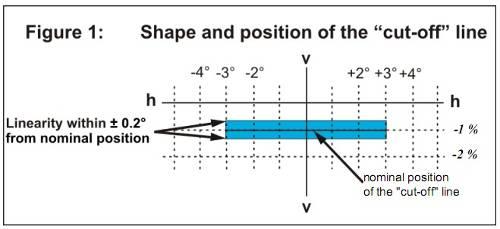
2. Shape of the cut-off line
2.1. Visual adjustment of the symmetrical passing-beam headlamp shall provide a horizontal line for adjustment of the symmetrical passing-beam headlamp extending to either side of the V-V line (see figure 1).
3. Adjustment of the symmetrical passing-beam headlamp
3.1. Horizontal adjustment:
The beam with the "cut-off" line shall be so positioned that the projected beam pattern appears approximately symmetrical to the V-V line.
3.2. Vertical adjustment:
After horizontal adjustment of the symmetrical passing-beam headlamp according to paragraph 3.1. above, the vertical adjustment shall be performed in such a way that the beam with its "cut-off" line is moved upwards from the lower position until the "cut-off" line is situated at nominal vertical position. For nominal vertical adjustment the "cut-off" line is positioned on the V-V line at 1% below the h-h line (250 mm).
If the horizontal part is not straight but slightly curved or inclined, the "cut-off" line shall not exceed the vertical range formed by two horizontal lines which are situated from 3° left to 3° right of the V-V line at 0.2° for Class B and 0.3° for Class A, C, and D headlamps above, and below the nominal position of the "cut-off" (see figure 1).
3.3. When the vertical adjustments of three different individuals differs by more than 0.2° for Class B and 0.3° for Class A, C, and D head lamps, the horizontal part of the "cut-off" line is assumed not to provide sufficient linearity or sharpness for performing visual adjustment. In this case the quality of "cut-off" shall be tested instrumentally for compliance with requirements as follows.
4. Measurement of the quality of "cut-off"
4.1. Measurements shall be performed by vertically scanning through the horizontal part of the "cut-off" line in angular steps not exceeding 0.05° or 22 mm at different distances.
- At a measurement distance of 10 m and a detector with a diameter of approximately 10 mm, or
- At a measurement distance of 25 m and a detector with a diameter of approximately 30 mm.
The measurement of the "cut-off" quality shall be considered acceptable if the requirements of the paragraph 4.1.2. comply with at least one measurement at 10 m or 25 m.
The scanning is performed upwards through the "cut-off" line along the vertical lines (figure 2) at −± 30 or ± 1310 mm from the V-V line. When so measured, the quality of the "cut-off" line shall meet the following requirements:
4.1.1. Not more than one "cut-off" line shall be visible
4.1.2. Sharpness of the cut-off line:
If scanned vertically through the horizontal part of the "cut-off" line along 2 lines that is ± 2,50 or ± 1092 mm from the V-V line (figure 1), the maximum value measured for:
G = (log EV - log E(V + 0.1°) )
is called the sharpness factor G of the "cut-off" line. The value of G shall not be less than 0.13 for Class B and 0.08 for Classes A, C, and D. The position the value of G is maximum is considered the position of the “cut-off” line.
4.1.3. Linearity: the part of the "cut-off" line which serves for vertical adjustment shall be horizontal from -30 or -1310 mm to +30 or +1310 mm of the V-V line. This requirement is deemed to be met if the vertical positions of the points with greatest values of G on the lines, which are positioned respectively 1.50 or 655 mm, 30 or 1310 mm from the left and right of the V-V line, do not differ by more than 0.2° or 87mm for Class B and 0.3° or 130 mm for Class A, C, and D head lamps from the position of the cut-off line.
5. Vertical adjustment:
If the "cut-off" line complies with the above quality requirements, vertical adjustment shall be performed by shifting the “cut-off” line mentioned in paragraph 4.1.2 to 250 mm below H-H line.

Figure 2. Positions of “cut-off”
APPENDIX 15
SYSTEMS OF INSTRUMENTS FOR TESTING PHOTOMETRIC CHARACTERISTICS OF HEADLAMPS
1. General requirements
1.1. The system of instruments shall be installed according to figure 1, including: dark room, measuring screen, photoreceptor, mounting, power supply unit (PSU), controller and monitor.

Figure 1: Arrangement of the test room
1- Dark room; 2- Measuring screen; 3- Photoreceptor; 4- Additional screen; 5- Controller and monitor; 6- Mounting; 7- PSU
Figure 2: Position of the photoreceptor on the measuring screen
Figure 3. Mounting according to principle 1

Figure 4. Mounting according to principle 2
1.2. Principles
The system shall be used according to one of the two following principles:
1.2.1. Principle 1: the photoreceptor is moved parallel to the plane of the measuring screen along the vertical axis (Z) and horizontal axis (X) to receive light from the tested headlamp (figure 2). The mounting shall be moved along the vertical axis (Z) - figure 3.
1.2.2. Principle 2: The photoreceptor shall only be moved along the vertical axis (Z). The mounting may be moved up and down, rotated around the vertical axis (Z) and horizontal axis (X) - figure 4.
2. Technical requirements
2.1. Dark room
The dark room shall be isolated or separated by partitions. The ceiling, the floor, and the walls of the dark room shall be covered with dark and unreflective materials. Additional curtains and blinds may be arranged in the dark room to minimize reflecting light during the test.
When no electrical equipment is used, the illumination at every position in the dark room must be 0 lux. No ambient light is allowed in the dark room.
The dark room must be spacious enough to install the instruments prescribed figure 1. The minimum distance from the photoreceptor to the front surface of the tested headlamp is 25 m. the width and height of the dark room must be sufficient to install the measuring screen and photoreceptor (figure 1) and measure the photometric characteristics of the driving beam and passing beam prescribed in Appendices 1 to 10.
2.2. Measuring screen
The measuring screen shall be installed according to figure 1. Its size must meet the requirements in Appendices from 1 to 10, and conform to the principles in 1.2. The projection shall be divided into squares in order to qualitatively determine the position of “cut-off” of the passing beam.
2.3. Photoreceptor
The effective area of the photoreceptor must meet the requirements in Appendices 1 to 10.
2.3.1. Principle 1: The photoreceptor shall be mounted and moved parallel to the plane of the measuring screen. The coordinates of the photoreceptor is determined horizontally and vertically. The steps of the photoreceptor shall be displayed on the monitor. The minimum step is 1 mm. The photoreceptor shall have an illumination scale with a tolerance of 0.01 lux and a measurement spectrum that meet the requirements in Appendices 1 to 10.
2.3.2. Principle 2: The photoreceptor is mounted and moved vertically. The scale of the photoreceptor shall conform to 2.3.1.
2.4. Control panel and monitor
The control panel and monitor shall be used to control the movement of the photoreceptor or the mounting in accordance with 2.3 and 2.5. The illumination, movements, rotating angles of the photoreceptor and mounting must be displayed.
2.5. Mounting
2.5.1. According to principle 1: the mounting must be able to hold the lamp still on the mounting plate throughout the test.
2.5.2. According to principle 2: The mounting must be able to hold the lamp still, move it a long the vertical axis (Z), rotate it around the vertical axis (Z) and horizontal axis (X) with 0.010 steps.
2.6. PSU
The PSU must supply and maintain sufficient DC voltage for the lamp throughout the test. The voltage supplied for the tested lamp shall be adjustable with a tolerance of 0.01V. The voltage and current intensity of the PSU must be displayed. The PSU must be able to measure or compensate for voltage drop on the line from the PSU to the tested lamp.
2.7. Colorimeter
The colorimeter must be able to demonstrate the colors of the beam produced by the lamp in trichromatic coordinates CIE with a tolerance of ± 0,002.