Nội dung toàn văn Decision 32/2007/QD-BKHCN testing of diagnostic x ray devices
|
MINISTRY OF SCIENCE
AND TECHNOLOGY |
SOCIALIST REPUBLIC
OF VIETNAM |
|
No. 32/2007/QD-BKHCN |
Hanoi, December 31, 2007 |
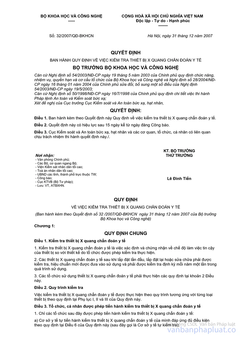
DECISION
TESTING OF DIAGNOSTIC X-RAY DEVICES
MINISTER OF SCIENCE AND TECHNOLOGY
Pursuant to the Government's Decree No. 54/2003/ND-CP dated May 19, 2003 defining functions, tasks, entitlements and organizational structure of the Ministry of Science and Technology and the Government's Decree No. 28/2004/ND-CP dated January 16, 2004 on amendments thereto;
Pursuant to the Government's Decree No. 50/1998/ND-CP dated July 16, 1998 elaborating the Ordinance on radiation safety and control;
At the request of Director of Nuclear and Radiation Safety Authority,
DECIDES:
Article 1. The statute on inspection of diagnostic x-ray devices is promulgated together with this Decision.
Article 2. This Decision comes into force after 15 days from the day on which it is published on the Official Gazette.
Article 3. Nuclear and Radiation Safety Authority, relevant organizations and individuals are responsible for implementation of this Decision./.
|
|
PP MINISTER |
DECISION
INSPECTION
OF DIAGNOSTIC X-RAY DEVICES
(Promulgated
together with Decision No. 32/2007/QD-BKHCN dated December 31, 2007 of the
Minister of Science and Technology)
Chapter 1:
GENERAL PROVISIONS
Article 1. Inspection of diagnostic x-ray devices
1. Inspection of diagnostic x-ray devices means determination and certification of reliability of the devices by testing bodies.
2. After a diagnostic x-ray device is installed, reinstalled or repaired must be inspected and calibrated before use and undergo at annual inspection throughout its use.
3. Clause 2 of this Article applies to organizations that use diagnostic x-ray devices (hereinafter referred to as “device users”).
Article 2. Inspection procedures
Inspection of diagnostic x-ray devices shall be carried out according to provisions of Appendices I through III of this document.
Article 3. Inspection of diagnostic x-ray devices
1. Only the following organizations may carry out inspection of diagnostic x-ray devices:
c) Health facilities that have diagnostic x-ray devices and fulfill the conditions specified in Article 6 of this document (hereinafter referred to as “self-testing facilities");
b) Organizations providing diagnostic x-ray device inspection services that fulfill the conditions specified in Article 7 of this document (hereinafter referred to as “testing service provider");
Self-testing facilities and testing service providers are referred to as “testing bodies”.
2. Individuals may only inspect diagnostic x-ray devices while working for the organizations specified in Clause 1 of this Article and fulfill the conditions specified in Clause 1 Article 6 of this document (hereinafter referred to as “tester").
Article 4. Responsibilities of Nuclear and Radiation Safety Authority
1. Carry out evaluation to recognize or license testing service providers.
2. Carry out inspections of adherence to regulations on inspection of diagnostic x-ray devices and take actions against violations within its authority.
3. Settle complaints and denunciations in inspection of diagnostic x-ray devices
Article 5. Inspection of testing bodies
1. Follow corresponding procedures for diagnostic x-ray devices specified in Appendices I through III of this document.
2. Annually calibrate inspecting devices.
3. Issue inspection results. Testing service providers shall prepare 02 copies of each record; 01 copy will be sent to the customer and the other retained.
4. Documents about inspection result shall be retained for at least 05 years.
5. Inform Nuclear and Radiation Safety Authority of changes of testers and send information about the new testers (Form 03 in Appendix VI).
6. Prepare and submit annual reports (by November 30) on inspection of diagnostic x-ray devices to Nuclear and Radiation Safety Authority (Form 01), the Department of Science and Technology and Provincial Department of Health (Form 02 in Appendix IV); prepare ad hoc reports at the request of these authorities.
7. Facilitate inspections by competent authorities.
8. Take responsibility for the results given.
Chapter 2:
CONDITIONS TO BE FULFILLED BY TESTING BODIES
Article 6. Self-testing facilities
A self-testing facility must:
1. Have at least 01 tester who:
a) has a bachelor’s degree or college degree and a certificate of completion of training in inspection of diagnostic x-ray devices and radiation safety issued by Nuclear and Radiation Safety Authority; or
b) has a bachelor’s degree in physics.
2. Have adequate inspecting devices according to the corresponding procedures specified in Appendix I through III enclosed herewith which are calibrated in accordance with Clause 2 Article 5 of this document.
3. Have a quality assurance program that complies with provisions in Appendix V enclosed herewith.
4. Have a certificate of eligibility to inspect diagnostic x-ray devices issued by Nuclear and Radiation Safety Authority.
Article 7. Testing service providers
A testing service provider must:
1. Fulfill the conditions specified in Clause 1 through 3 of Article 6 of this document.
2. Have a license to provide radiation safety services issued by Nuclear and Radiation Safety Authority.
Chapter 3:
RECOGNITION OF ELIGIBILITY FOR SELF-INSPECTION, LICENSING RADIATION SAFETY SERVICES
Article 8. Recognition of eligibility for self-inspection
1. A self-testing facility shall submit the application for recognition of its eligibility for self-inspection of diagnostic x-ray devices (Appendix VI) to Nuclear and Radiation Safety Authority.
2. Within 30 working days from the day on which the valid application is received, Nuclear and Radiation Safety Authority shall process it and evaluate the applicant’s eligibility in accordance with Clause 1 through 3 Article 6 of this document, then decide whether to grant the certificate of eligibility for inspection of diagnostic x-ray devices or reject the application. The certificate of eligibility for inspection of diagnostic x-ray devices must specify that: The applicant must fulfill the responsibility specified in Article 5 and conditions specified in Clause 1 through 3 Article 6 of this document.
3. Inspection and evaluation costs shall be paid by the applicant.
Article 9. Licensing radiation safety services
1. A testing service provider shall submit the application for the license to provide radiation safety services (Appendix VI) to Nuclear and Radiation Safety Authority.
2. Within 30 working days from the day on which the valid application is received, Nuclear and Radiation Safety Authority shall process it and evaluate the applicant’s eligibility in accordance with Clause 1 Article 7 of this document, then decide whether to grant the license or reject the application. The license to provide radiation safety services must specify that: the applicant must fulfill the responsibility specified in Article 5 and conditions specified in Clause 1 through 3 Article 6 of this document.
3. The applicant shall pay the fees and charges specified in Decision No. 38/2006/QD-BTC dated July 24, 2006 of the Ministry of Finance.
Article 10. Effective period and extension of certificate of eligibility to inspect diagnostic radiography and license to provide radiation safety services
1. A certificate of eligibility to inspect diagnostic radiography and license to provide radiation safety services is effective for 3 years.
2. An application for extension (Appendix VII) shall be submitted to Nuclear and Radiation Safety Authority at least 60 days before the certificate or license expires if its holder wishes to have it extended.
3. Within 30 working days from the day on which the valid application is received, Nuclear and Radiation Safety Authority shall process it and decide whether to grant extension or reject the application.
4. The applicant for extension shall pay the evaluation costs or fees and charges specified in Decision No. 38/2006/QD-BTC.
Chapter 4:
IMPLEMENTATION
Article 11. Actions against violations
1. A testing service provider that fails to fulfill the conditions specified in the license to provide radiation safety services shall be dealt with in accordance with the Government's Decree No. 51/2006/ND-CP
2. A self-testing facility that fails to fulfill the conditions specified in the certificate of eligibility to inspect diagnostic radiography shall be dealt with in accordance with the Government's Decree No. 51/2006/ND-CP
Article 12. Guidelines for implementation
1. A decision on recognition of eligibility to inspect diagnostic x-ray devices issued by the Directorate for Standards, Metrology, and Quality before the effective date Decision No. 13/2007/QD-BKHCN dated July 06, 2007 of the Minister of Science and Technology is still as effective as a license to provide radiation safety services until its expiration. After such decision expires, its holder shall apply for the certificate of eligibility to inspect diagnostic x-ray devices or license to provide radiation safety services in accordance with this document.
2. Nuclear and Radiation Safety Authority is responsible for providing guidelines for implementation of this document.
3. Difficulties that arise during the implementation of this document should be reported to the Ministry of Science and Technology for instructions./.
APPENDIX 1:
PROCEDURES
FOR INSPECTION OF MEDICAL CONVENTIONAL DIAGNOSTIC X-RAY DEVICES
(Promulgated together with Decision No. 32/2007/QD-BKHCN dated December 31,
2007 of the Minister of Science and Technology)
1. Definitions
1.1. Peak kilovoltage (kVp): The rectified voltage between the anode and cathode of the x-ray tube.
1.2. Exposure time: the period over which the x-ray beam is generated by the device.
1.3. Tube current: the current from the anode to the cathode of the x-ray tube during the exposure time.
1.4. mAs: multiplication of tube current and exposure time.
1.5. mR/mAs: ratio of radiation dose to mAs.
1.6. Effective focal spot size: effective size of the focal spot to generate x-ray.
1.7. Perpendicularity of x-ray beam: deviation of the x-ray beam perpendicular to the beam receptor.
1.8. Beam alignment: alignment of the light field of the collimator and the radiated field created by the x-ray tube.
1.9. Half-value layer (HVL): the thickness of the filter at which the radiation intensity (exposure) is reduced by one half of its original value without a filter.
1.10. Patient dose (PD): the radiation dose (including backscatter) to which the patient is exposed during the imaging process and expressed as Gray (Gy, 1Gy = 1J/kg tissue)
2. Tests
The tests specified in Table 1 of this Appendix must be carried out in succession.
Table 1
|
No. |
Test |
Article |
Testing period |
|
|
Initial |
Periodic |
|||
|
1 |
External test |
5.1 |
x |
x |
|
2 |
Peak kilovoltage |
5.2 |
x |
x |
|
3 |
Exposure time |
5.3 |
x |
x |
|
4 |
Tube current |
5.4 |
x |
x |
|
5 |
mAs |
5.5 |
x |
x |
|
6 |
mR/mAs |
5.6 |
x |
x |
|
7 |
Effective focal spot size of x-ray tube |
5.7 |
x |
x |
|
8 |
Perpendicularity |
5.8 |
x |
x |
|
9 |
Beam alignment |
5.9 |
x |
x |
|
10 |
HVL |
5.10 |
x |
x |
|
11 |
PD |
5.11 |
x |
x |
|
12 |
Exposure mode |
5.12 |
x |
x |
3. Test tools
The test tools specified in Table 2 of this Appendix must be used for testing.
Table 2
|
No. |
Test tool |
Specifications |
|
1 |
Multifunction meter |
Voltage range: (50÷165) kV, resolution: 0.1 kV, accuracy: ± 2%; Time range: (0÷20) s, accuracy ± 5%; Current range: (10÷1000) mA, accuracy ± 2%. |
|
2 |
Focal spot test tool
|
Resolution: (0.84÷5.6) line pairs/mm |
|
3 |
Beam alignment test tool
|
According to international standards |
|
4 |
Ionization chamber-type dosimeter |
Range: (0001÷2) R. Accuracy: ± 7 % |
|
5 |
Filters |
Aluminum, purity: 99.99%; size: 10x10 cm; thickness: 1 mm |
|
6 |
Test phantom (only required when measuring patient dose) |
Tissue-equivalent materials |
4. Testing conditions
Specified in the manual of the tested device
5. Testing
5.1. External test
5.1.1. Check the functionality of the device. Check the device profile: manufacturer, model, year of manufacturing, date on which the device is put into operation, specifications (kVp, mA).
5.1.2. Check the switches (or buttons of indicators): power source voltage, kVp, mA, s (exposure time), mAs, is the focal spot effective in the acceptable range.
5.1.3. Check the mechanical operation of the patient’s table, the tube housing and movement system, the beam control unit and cassette tray must be moved easily and safely. The calibrating tube must have adequate brightness; the center line of the beam must be aligned with the center line of the table. The braking system is operational.
5.1.4. Check the mechanical system of the x-ray device.
5.1.4.1. Check the mechanical operation of the x-ray tube housing.
5.1.4.2. Check the accuracy of the tube navigation system.
5.1.4.3. Check the accuracy of the distance from the focal spot to the table.
5.1.4.4. Check the accuracy of the table movement along various axes.
5.1.4.5. Check the movement of the collimator.
5.2. Peak kilovoltage
5.2.1. Peak kilovoltage (kVp)
The multifunction meter must be so placed on the table of the x-ray device that its radiation-sensitive window is aligned with the x-ray field of the x-ray device at a distance of 75 cm from the focal spot of the tube. The beam will be then generated according to predetermined mA and time. Set the kVp from low to high on the control panel and generate the x-ray beam, record the kVp displayed by the meter.
5.2.2. Determination of high voltage waveform
Place multifunction meter on the table of the x-ray device and generate the x-ray beam, then the meter will display the waveform of the device. The high voltage waveform may be a half-wave phase; a whole-wave phase; 3 phases, 6 pulses; 3 phases, 12 pulses and high frequency.
5.2.3. Accuracy of kVp
The accuracy of kVp is determined by maximum deviation between the recorded kVp and nominal kVp on the control panel.
(kVps - kVpm)max
UkVp = _____________________________ . 100%
kVpm
Where:
UkVp : Accuracy of kVp while imaging, (%);
kVps : nominal value of kVp on the control panel, (kV);
kVpm : value of kVp recorded, (kV).
UkVp must not exceed ±5%.
5.2.4. Repeatability of kVp
Repeatability of kVp is determined by repeating 3 random kVp, generate the x-ray beam and measure the actual kVp of each time. Deviation between recorded kVps and mean kVp after 3 times:
(kVpi,m - kVpm,tb)max
RkVp = _____________________________________ . 100%
kVpm,tb
Where:
RkVp : Repeatability of kVp, (%);
kVpi,m : maximum or minimum kVp measured at time i at the same nominal voltage, (kV);
kVpm,tb : mean kVp after 3 times at the same nominal voltage, (kV).
RkVp must not exceed ± 5%.
5.2.5. Variation of kVp at various mA and mAs.
Set the mA and mAs at their mean values, then generate the x-ray beam in the ascending order of the mAs but maintain the set kVp on the control panel. Measure the kVp. The change of kVp according to each mA and mAs is evaluated according to accuracy of kVp.
The variation of kVp must not exceed ± 5%
5.3. Exposure time
5.3.1. Accuracy of exposure time
- Place the multifunction meter at the center of the x-ray field whose size is suitable for the radiation-sensitive area of the meter, 75 cm from the x-ray tube.
- Generate the x-ray beam with at least 5 time values e.g. 0.3s; 0.5s; 0.7 s; 1.0 s; 1.2 s.
Deviation between nominal and recorded value:
Ts - Tm
Ut = __________________________ . 100%
Tm
Where:
Ut : deviation of exposure time, (%);
Ts : nominal exposure time, (s);
Tm : exposure time measured at set time, (s).
Ut must not exceed ± 10 %.
5.3.2. Stability of exposure time
Stability of exposure time is determined by repeating 3 random exposure times, generate the x-ray beam and measure the actual duration of each time. Determine maximum deviation of duration with the mean duration after 3 times at the same nominal value:
(Ti,m - Tm,tb)max
Rt = _____________________________________ . 100%
Tm,tb
Where:
Rt : stability of exposure time, (%);
Ti,m : maximum or minimum measured exposure time at time i, (s);
Tm,tb : mean exposure time after 3 times, (s).
Rt must not exceed ± 5%.
5.4. Tube current
5.4.1. Stability of mA
- Place the multifunction meter at the center of the x-ray field whose size is suitable for the radiation-sensitive area of the meter, 75 cm from the x-ray tube.
- Set fixed kVps and times, then generate the x-ray beam with a suitable mA and measures the current (I) five times. Record the reading and calculate:
(Ii,m - Im, tb)max
RI = ____________________________________ . 100%
Im,tb
Where:
RI : stability of current, (%);
Ii,m : maximum or minimum tube current measured at time i, (mA);
Im,tb : mean tube current after 5 times, (mA).
RI must not exceed ±5%.
5.4.2. Linearity of tube current (LmA)
Generate the x-ray beam with increasing mA, maintain kVp and time. Record the current on the multifunction meter and calculate:
mAm,i
LmA= ________________________ . 100%
mAs,i
Where:
LmA : Linearity of current, (%);
mA m,i : measured current in the nominal range, (mA);
mAs,i : nominal current on the device at time i, (mA).
LmA must be between 85% and 115%.
5.5. mAs
5.5.1. Stability of mAs
- Place the multifunction meter at the center of the x-ray field whose size is suitable for the radiation-sensitive area of the meter, 75 cm from the x-ray tube.
- Set fixed kVps and times, then generate the x-ray beam with a suitable mAs and measure the mAs five times. Record the mAs on the multifunction meter and calculate:
(mAsi,m - mAsm,tb) max
R mAs = _____________________________________ . 100%
mAsm,tb
Where:
R mAs : stability of mAs, (%);
mAsi,m : maximum or minimum mAs measured at time i, (mAs);
mAsm,tb : mean mAs after 5 times, (mAs).
Rmas must not exceed 5%.
5.5.2. Linearity of mAs
Generate the x-ray beam with increasing mAs, maintain kVp and exposure time. Record the mAs on the multifunction meter and calculate:
mAsm,i
LmAs = _______________________ .100%
mAss,i
Where:
LmAs : Linearity of mAs, (%);
mAsm,i : mAs measured at time i, (mAs);
mAss,i : nominal mAs on the device at time i, (mAs).
LmAs must be between 85% and 115%.
5.6. Exposure
Linearity and repeatability of exposure of an x-ray device is determined as follows:
Measure exposure 3 times, determine mR/mAs of three to four values of current (mA) and exposure time (s).
mRmax - mRmin
5.6.1 Repeatability of exposure (%) = ___________________________________ . 100%
2.mRtb
Where:
mRmax : maximum exposure, (mR);
mRmin : minimum exposure, (mR);
Rtb : mean exposure of 3 or 4 values, (mR).
Repeatability of exposure must not exceed ±10 %.
5.6.2. Linearity of mR/mAs
(mR/mAs)max - (mR/mAs)min
LmR/mAs (%) = ________________________________________________ . 100%
2.(mR/mAs)tb
LmR/mAs must not exceed ±10 %.
5.6.3. Exposure (mR) according to kVp
Place the dosimeter at the center of the x-ray field whose size is suitable for the radiation-sensitive area of the dosimeter, 75 cm from the x-ray tube.
Set fixed mA and times, then generate the x-ray beam with a suitable kVp and measures the exposure (mR) five times. Record the result.
Repeat this with two more values of kVp.
Variation factor of exposure is calculated as follows:
Variation factor = 
Where:
n : number of measurements (five);
![]() : mean
reading on the dosimeter after 5 measurements, (mR);
: mean
reading on the dosimeter after 5 measurements, (mR);
Xi : reading on the dosimeter after each time the beam is generated, (mR).
Variation factor must not exceed ±10 %.
5.7. Effective focal spot size of x-ray tube
- Place the film on the table at a distance of 61 cm from the x-ray tube;
- Place the test tool on the film surface so that its upper surface is perpendicular to the beam generated;
- Generate the x-ray beam with suitable kVp and mAs;
- Repeat the measurement with various focal spots of the device.
Resolution of the x-ray tube can be evaluated according to the test plate and the shades of 6 lines in two different directions on the film.
Table 3
|
Classification by resolution |
line pairs/mm |
Effective focal spot size |
|
1 2 3 4 5 6 7 8 9 10 11 12 |
0.84 1.00 1.19 1.14 1.63 2.00 2.38 2.83 3.36 4.00 4.76 5.66 |
4.3 mm 3.7 mm 3.1 mm 2.6 mm 2.2 mm 1.8 mm 1.5 mm 1.3 mm 1.1 mm 0.9 mm 0.8 mm 0.7 mm |
Acceptable deviation of an effective focal spot size > 1.5 mm is 0.3f; Acceptable deviation of an effective focal spot size < 1.5="" mm="" is="" 0.4f="" where="" f="" is="" the="" nominal="" focal="" spot="" size.="">
5.8. Perpendicularity of x-ray beam
- Place the patient table in the horizontal position and use a bubble lever to check its balance;
- Place the cassette containing film with medium sensitivity at the center of the table. Place the tube perpendicular to the table surface at a distance of 1 m from the film;
- Place the test tool on the cassette surface;
- Align the center of the light field of the collimator with the center of the test tool;
- Generate the x-ray beam with suitable kVp and mAs. Carry out film development;
- If two balls are shown to be aligned, perpendicularity is <>0;
- If the upper ball lies on the inner circle, perpendicularity is about 1.50;
- If the ball lies between the inner circle and outer circle, perpendicularity is between 1.50 and 30.
Acceptable perpendicularity is 1.50.
5.9. Alignment of light field and x-ray field
- Place the patient table horizontally and use a bubble lever to check its balance;
- Place the cassette containing film with medium sensitivity at the center of the table. Place the tube perpendicular to the table surface at a distance of 1 m from the film;
- Place the beam alignment test tool on the cassette surface;
- Align the center of the light field of the collimator with the center of the test tool;
- Generate the x-ray beam with suitable kVp and mAs. Carry out film development;
- Evaluate the alignment of light field and x-ray field.
Record X, X', Y and Y'.
Record sizes of the light field and x-ray field (X + X' and Y + Y')
Record the values of (X + X' + Y + Y').
5.9.1. Deviations
X = --------- cm % of TFD
Y = --------- cm % of TFD
X' = -------- cm % of TFD
Y' = -------- cm % of TFD
Acceptable deviation is 2% of TFD (Target to Film Distance).
5.9.2. Differences in sizes of the light field and x-ray field
X + X' = ........... cm % of TFD
Y + Y' = .......... cm % of TFD
Acceptable difference is 3%.
5.9.3. Difference between length and width of the light field and x-ray field
X + X' + Y + Y' = ............. cm % of TFD
Acceptable difference is 4%.
5.10. Evaluation of HVL and total filtration thickness of x-ray tube
- Place the ionization chamber-type dosimeter at the center of the x-ray field at a distance of 75 cm from the x-ray tube;
- Set kVp = 80 kV; mAs = 15, generate the x-ray beam and record readings on the dosimeter. Repeat five times and calculate the mean value;
- Insert a filter with a thickness of 0.5 mm between the collimator and dosimeter, then repeat the measurement. Repeat the measurement with filters with a thickness of 1 mm, 2 mm, 3 mm and 4 mm;
- Determine the HVL using a graph, one axis of which indicates the doses measured and the other filtration thickness;
- Refer to Table 4 and 5 to evaluate total filtration thickness.
Total filtration thickness at 80 kVp must not fall below 2.0 mm Al.
Table 4
Total filtration thickness by HVL in single-phase x-ray machines
|
Total filtration thickness (mm Al) |
kV and HVL (mm Al) |
|||||||||
|
30 |
40 |
50 |
60 |
70 |
80 |
90 |
100 |
110 |
120 |
|
|
0.5 |
0.36 |
0.47 |
0.58 |
0.67 |
0.76 |
0.84 |
0.92 |
1.00 |
1.08 |
1.16 |
|
1.0 |
0.55 |
0.78 |
0.95 |
1.08 |
1.21 |
1.33 |
1.46 |
1.58 |
1.70 |
1.82 |
|
1.5 |
0.78 |
1.04 |
1.25 |
1.42 |
1.59 |
1.75 |
1.90 |
2.08 |
2.25 |
2.42 |
|
2.0 |
0.92 |
1.22 |
1.49 |
1.70 |
1.90 |
2.10 |
2.28 |
2.48 |
2.70 |
2.90 |
|
2.5 |
1.02 |
1.38 |
1.69 |
1.95 |
2.16 |
2.37 |
2.58 |
2.82 |
3.06 |
3.30 |
|
3.0 |
|
1.49 |
1.87 |
2.16 |
2.40 |
2.62 |
2.86 |
3.12 |
3.38 |
3.65 |
|
3.5 |
|
1.58 |
2.00 |
2.34 |
2.60 |
2.86 |
3.12 |
3.40 |
3.68 |
3.95 |
Table 5
Total filtration thickness by HVL in three-phase x-ray machines
|
Total filtration thickness (mm Al) |
kV and HVL (mm Al) |
||||||||
|
60 |
70 |
80 |
90 |
100 |
110 |
120 |
130 |
140 |
|
|
2.5 |
2.2 |
2.4 |
2.7 |
3.1 |
3.3 |
3.6 |
4.0 |
|
|
|
3.0 |
2.3 |
2.6 |
3.0 |
3.3 |
3.6 |
4.0 |
4.3 |
4.6 |
5.0 |
|
3.5 |
2.6 |
2.9 |
3.2 |
3.6 |
3.9 |
4.3 |
|
|
|
5.11. Determination of patient dose according to basic safety standards (BSS) (mandatory to machines having automatic exposure control)
Measure the patient dose using an ionization chamber and thermoluminescent dosimeter on the test phantom.
Mean patient dose must not exceed 0.4 mGy in chest X-ray (high frequency) and 10 mGy in abdominal cavity x-ray.
5.12. Exposure modes
5.12.1. Check the movement of the collimator.
5.12.2. Check the foot switch.
5.12.3. Check the switch on the screen.
5.12.4. Check the timer switch.
5.12.5. Check the alignment of the screen and central beam.
5.12.6. Check the image quality on the screen.
5.12.7. Measure the dose rate.
Place the dosimeter at the center of the beam on the table. Operate the generator with a suitable kVp and current, then measure the dose rate. Dose rate must not exceed 0.5 Gy per minute.
5.12.8. Check peak kilovoltage (see 5.2.1).
6. Other procedures
6.1. Use form 01 to record test results.
6.2. An x-ray device that is tested according to section 5 will receive a testing certificate (form 02).
6.3. The test cycle is 01 year.
APPENDIX 2:
PROCEDURES
FOR INSPECTION OF FLUOROSCOPIC TV X-RAY DEVICES
(Promulgated together with Decision No. 32/2007/QD-BKHCN dated December 31,
2007 of the Minister of Science and Technology)
1. Definitions
1.1 Peak kilovoltage (kVp): The rectified voltage between the anode and cathode of the x-ray tube.
1.2. Exposure time: the period over which the x-ray beam is generated by the device.
1.3. Tube current: the current intensity from the anode to the cathode of the x-ray tube during the exposure time.
1.4. mAs: multiplication of tube current and exposure time.
1.5. mR/mAs: ratio of radiation dose to mAs.
1.6. Perpendicularity of x-ray beam: deviation of the x-ray beam perpendicular to the beam receptor.
1.7. Half-value layer (HVL): the thickness of the filter at which the exposure is reduced by one half of its original value without a filter.
1.8 Absorption rate: the absorbed dose per unit of time.
2. Tests
The tests specified in Table 1 of this Appendix must be carried out in succession.
Table 1
|
No. |
Test |
Article |
Testing period |
|
|
Initial |
Periodic |
|||
|
1 |
External test |
5.1 |
+ |
+ |
|
2 |
Peak kilovoltage |
5.2 |
+ |
+ |
|
3 |
Dose rate |
5.3 |
+ |
+ |
|
4 |
Monitor quality |
5.4 |
+ |
+ |
|
5 |
Size of the light field of fluoroscopic tube |
5.5 |
+ |
+ |
|
6 |
Ray filtration and HVL of x-ray tube |
5.6 |
+ |
+ |
|
7 |
Image quality - Distortion - High contrast resolution - Low contrast resolution - Contrast threshold |
5.7 |
+ |
+ |
|
8 |
Imaging functions according to Appendix I |
|
+ |
+ |
3. Test tools
The test tools specified in Table 2 of this Appendix must be used for testing.
Table 2
|
No. |
Test tool |
Specifications |
|
1 |
Multifunction meter |
kVp range: 50 kV÷165 kV, Resolution: 0.1 kV, Accuracy: 2%; Time range: (0.1 ÷ 20) s Current range: 1 mA ÷ 600 mA |
|
2 |
Dose rate monitor |
Measurement range 0.1 mGy/min ÷ 100 mGy/min (10 mR/min ÷ 10 R/min) |
|
3 |
Image quality test tool (test phantom) |
Image quality Grayscale Field of view diameter Maximum spatial resolution Contrast threshold Low contrast sensitivity |
|
4 |
Tape measure |
Range: 2 m |
|
5 |
Cassette |
X-ray film |
|
6 |
Lead plates |
Thickness: 1.5 mm |
|
7 |
Aluminum plates |
Thickness: 1 mm, 2 mm, 3 mm |
4. Testing conditions
The conditions specified in the manual of the fluoroscopic TV x-ray device must be fulfilled.
5. Testing and calibration
5.1. External test
5.1.1. Check the functionality of the device. Check the device profile: manufacturer, model, year of manufacturing, date on which the device is put into operation, specifications (kVp, mA).
5.1.2. Check the switches (or buttons of indicators): power source voltage, kVp, mA, s (exposure time), mAs, is the focal spot effective in the acceptable range. The indicators must display correct values and the overload alarm must be functional.
5.1.3. Check the mechanical operation of the patient table, the tube housing and tube movement mechanism, the beam control unit and cassette tray must be moved easily and safely. The calibrating tube must have adequate brightness; the center line of the beam must be aligned with the center line of the table.
5.2. Peak kilovoltage
5.2.1. Peak kilovoltage
Place the multifunction meter on the table of the x-ray device and generate the x-ray beam at predetermined mA and time. Set the kVp from low to high on the control panel and generate the x-ray beam, record the kVp displayed by the meter. Repeat some values of kVp, generate the x-ray beam and measure.
Measure kVp at (60, 70, 80, 90, 100) kVp at a 2 mA or automatic current.
5.2.2. Determination of high voltage waveform
High voltage waveforms are determined by the multifunction meter: Place the multifunction meter on the table and generate the x-ray beam, the meter will display the waveform, including: single-phase full-phase; 3 phases and 6 pulses; 3 phases, 12 pulses and high frequency.
5.2.3. Accuracy of kVp
The accuracy of kVp is determined by maximum deviation between recorded high voltages corresponding to nominal voltage on the control panel.
(kVps - kVpm)max
UkVp = ________________________________ . 100%
kVpm
Where:
UkVp : accuracy of kVp, (%);
kVps : nominal values of kVp on the control panel, (kV);
kVpm : measured kVp, (kV)
UkVp must not exceed ±10.
5.2.4. Repeatability of kVp
Generate the x-ray beam at a random kVp 3 times and measure the actual kVp after each time. Determine the deviation between measured kVps and mean kVp after 3 times.
(kVpi,m - kVpm,tb)max
RkVp = ______________________________________ . 100%
kVpm,tb
Where:
RkVp : repeatability of kVp, (%)
kVpi,m : maximum or minimum kVp at the same nominal kVp, (kV);
kVpm,tb : mean kVp at the same nominal kVp
RkVp must not exceed ± 5%.
5.2.5. Variation of kVp against mA.
- Set kVp at 80 kV and 2 mA, generate the x-ray beam and measure kVp.
- Measure similarly to 5.2.1.
- Evaluate the variation of kV.
Variation of kVp must not exceed ±5%.
5.3. Dose rate
Test procedures:
1. Place the absorbent material (20 cm of water or lead plate) on the table at the center of the x-ray field, then place the dosimeter on the absorbent material.
2. Generate the x-ray beam at 80 kV and a current between 2 mA and 4 mA to achieve sharpest image quality. Measure the dose rate (mGy/min).
3. Switch to automatic exposure mode and measure the dose rate (mGy/min).
4. Switch to maximum exposure mode and measure the dose rate (mGy/min).
Note: The dose rate must be measure over the entire x-ray field;
The dosimeter must be of ionization chamber-type.
Acceptable deviation of dose rate must not exceed ±10%.
5.4. Check the monitor quality
Procedures:
1. Place the absorbent material (20 cm of water or lead plate) on the table at the center of the x-ray field, then place the dosimeter on the absorbent material.
2. Switch to BRIGHT mode, set peak kilovoltage at 70 kVp and adjust mA until the image is sharpest.
3. Adjust CONTRAST and BRIGHT until the grayscales and circles on the monitor are clearly visible.
4. Observe the image at a distance of 4 times the diameter of the monitor in the machine chamber.
Note:
- Turn CONTRAST to minimum value;
- Adjust BRIGHT until the image is sharpest;
- Adjust CONTRAST until the grayscales are clearly visible.
5.5. Check x-ray field size of the fluoroscopic tube
Procedures:
- Set the maximum source to image distance (SID);
- Adjust the size of the light field of the fluoroscopic tube
- Switch to automatic beam generation mode and adjust brightness in (1 ÷ 2) seconds;
- Test the adjustability of x-ray field;
- Test the magnification of the fluoroscopic tube
5.6. Ray filtration and HVL of x-ray tube
Procedures:
- Set the maximum SID;
- Cover the second fluoroscopic scope with a lead plate;
- Place the dosimeter on the lead plate;
- Generate the x-ray beam at kVp = 80 kV and automatic mA;
- Measure the dose rate without the aluminum filter 3 times and calculate the mean value;
- Measure the dose rate with aluminum plates with thickness of 1 mm, 2 mm, 3 mm, 4 mm;
- Draw a graph on the logarithmic paper and determine HVL.
Note: Only measure HVL within the working kVp and mA range of the device;
HVL = (2.8 – 4) mmAl at 80 kVp.
5.7. Image quality
5.7.1. Distortion
a) Place the phantom at the center of the x-ray field.
b) Set kV and mA automatically, then generate the x-ray beam for a suitable period of time.
Distortion is calculated as follows:
|
Distortion = [ |
Xmax |
1 ] . 100 |
|
n – Xcenter |
Where:
Xmax : diagonal of the largest square;
Xcenter : diagonal of the square at the center of the image;
n : divisor of the diagonal or the large square.
Acceptable distortion is 5%
- Mark the center of the measuring device and center of the monitor. Evaluate the deviation;
- Test with various field sizes.
c) Evaluate the result;
- The image of the monitor shows no distortion;
- The center of the beam is aligned with the center of the monitor.
5.7.2. High-contrast resolution
a) Place the test tool at the center of the x-ray field.
b) Set kV and mA automatically, then generate the x-ray beam for a suitable period of time to achieve a sharp image.
- Count the number of clearly visible lines on the monitor;
- The test is run with various sizes of x-ray field;
- 1.0 line pair must be clearly visible with an x-ray field of 23 cm; and 1.4 line pairs/mm must be clearly visible with an x-ray field of 15 cm.
5.7.3. Low-contrast resolution
a) Place the test tool at the center of the x-ray field.
b) Set kV and mA automatically, then generate the x-ray beam for a suitable period of time.
- Count the visible circles on the monitor at low contrast;
- The test is run with various sizes of x-ray field;
- 5 circles must be clearly visible with an x-ray field of 23 cm; and 6 circles must be clearly visible with an x-ray field of 15 cm.
Note:
A line phantom may be used to measure contrast;
- The resolution must be low over the entire field of view;
- The most inner circles must be visible.
5.7.4. Contrast threshold
a) Place the test tool at the center of the x-ray field.
b) Set kV and mA automatically, then generate the x-ray beam for a suitable period of time.
- Count the visible large circles on the monitor at low contrast;
- The test is run with various sizes of x-ray field;
- With 9/10 visible circles, the threshold is smaller than 5%.
Note: - A line phantom may be used to measure contrast;
- The contrast threshold must be maintained over the entire field of view;
- The most inner circles must be visible.
6. Other procedures
6.1. Use form 01 to record test results.
6.2. An x-ray device that is tested according to section 5 will receive a testing certificate (form 02).
6.3. The test cycle is 01 year.
APPENDIX 3:
PROCEDURES
FOR INSPECTION OF CT SCANNERS
(Promulgated together with Decision No. 32/2007/QD-BKHCN dated December 31,
2007 of the Minister of Science and Technology)
1. Definitions
1.1. Computed tomography dose index (CTDI)
The integration limit of dose profile along a line perpendicular to the slice surface (z-axis) with a value from -7T to +7T (T is the nominal slice width) divided by (:) product of the nominal slice width and tomography sections (N) imaged in a single scan.
+7T D(z)
CTDI = ò ____________ dz
-7T N.T
Where:
T : nominal slice width
N : number of tomography sections in a single scan
D(z) : radiation dose profile along the z-axis.
Unit of CTDI: Gy/mAs
1.2. CT number
A quantity that represents the mean x-ray attenuation associated with each elemental area of the CT image.
Note: CT number is expressed as Hounsfield (HU) Measured values of attenuation are converted into CT numbers as follows:
mmaterial - mwater
CT number of material = _________________________ . k
m water
Where:
k: a
coefficient provided in the manual.
m: linear attenuation coefficient.
The CT number of water is 0, water is 1000.
1.3. Dose profile
A quantity that depends on the dose along the z-axis.
1.4. Full width at half-maximum
The distance between the points on a curve at which the intensity is equal to half of its maximum value.
1.5. Region of interest (ROI)
A localized part of an image which is of particular interest at a given time.
1.6. Spatial resolution (High-contrast resolution)
The ability to differentiate different elements of an image when difference in attenuation between the elements and the background is higher than noise.
1.7. Mean CT number
The mean value of CT numbers in an ROI.
1.8. Noise
Variation of a CT number from a mean value in a defined area in the image of a uniform material. Amount of noise is indicated by standard deviation of a CT number of a uniform substance in the ROI
1.9. Slice width
Width of the x-ray beam going through the patient.
1.10. Nominal slice width
Slice width on the control panel of the scanner.
Note:
- The difference in attenuation coefficient between the subject and background causing a difference of a few hundred HU is considered considerable.
- High-contrast resolution is corresponding to spatial resolution.
1.11. Uniformity
Consistency of the building work number in the image of a uniform substance across the scan field.
2. Tests
The tests specified in Table 1 of this Appendix must be carried out in succession.
Table 1
|
No. |
Test |
Article |
Testing period |
|
|
Initial |
Periodic |
|||
|
1 |
Peak kilovoltage |
5.1 |
x |
x |
|
2 |
mA and mAs |
5.2 |
x |
x |
|
3 |
Noise, mean CT number, uniformity |
5.3 |
x |
x |
|
4 |
Spatial resolution |
5.4 |
x |
x |
|
5 |
High-contrast resolution |
5.5 |
x |
x |
|
6 |
Slice width |
5.6 |
x |
x |
|
7 |
Radiation dose |
5.7 |
x |
x |
|
8 |
Patient table |
5.8 |
x |
x |
|
9 |
Patient dose |
5.9 |
x |
x |
3. Test tools
The test tools specified in Table 2 of this Appendix must be used for testing.
Table 2
|
No. |
Test tools |
Specifications |
|
1 |
CT scanner phantoms |
According to international standards |
|
2 |
Multifunction meter |
Voltage range: (50÷165) kV, Accuracy: 0.1 kV; Time range: (0.1 ÷ 20) s Current range: (10÷1000) mA |
|
3 |
Ionization chamber-type dosimeter |
Range: (0.001÷100) R |
|
4 |
Measure |
Range: 3 mm; division: mm |
Note: All test tools used for testing must have effective certificates of calibration.
4. Testing conditions
- Ambient temperature not exceeding 300 C;
- Humidity not exceeding 85%;
- Source voltage variation not exceeding 5%.
5. Testing
5.1. Peak kilovoltage
See 5.2 of Appendix I.
5.2. mA and mAs
See 5.4 and 5.5 of Appendix I.
5.3. Noise, mean CT number and uniformity
5.3.1. Method
Noise, mean CT number and uniformity are evaluated by determining mean value and standard deviation of CT numbers in the ROI.
5.3.2. Test procedures
Place the center of the test tool inside the gantry (on the patient bed) to achieve uniform environment at the center of the scan field. The position of the test tool must be marked or noted.
After being placed, the test tool will be scanned with a set of suitable parameters (kVp, mAs, geometric layout).
Noise, mean CT number and uniformity are evaluated by determining mean value and standard deviation of CT numbers in the ROI. Find CT number in the ROI. Place the test tool at 3, 6, 9 and 12 o’clock positions at a distance of 1 cm from one another. The positions must be noted.
- The ROI must contain at least 100 pixels;
- The Central ROI does not have to overlap the ROI near the edge of the test tool;
- The ROI diameter must not exceed 10% of the image diameter of the test tool.
5.3.3. Data evaluation
Noise must be evaluated by comparing standard deviation of CT numbers at the center of the ROI with the baseline value to determine whether it is acceptable.
The mean CT number at the center of the ROI must be evaluated by comparing its value with the baseline value to determine whether it is acceptable.
Uniformity must be evaluated by comparing mean CT numbers of the ROIs at the center with those near the edge of the ROI. These tasks are compared with the baseline values to determine whether they are acceptable.
5.3.4. Acceptable standards
Noise must not exceed ±10% or 0.2 HU.
The mean CT number of the Central ROI must not exceed ±4 HU.
Regarding uniformity, the mean CT number of the central ROI and peripheral ROI must not deviate from more than 2 HU from the baseline value.
5.4. Spatial resolution
5.4.1. Test procedures
Place the test tool in the gantry at the center of the scan field.
The test pieces must be placed at a 450 angle from the horizontal axis of the patient bed.
The position of the phantom must be noted.
Run the scan after the phantom is properly placed in the gantry.
5.4.2. Data evaluation
A circular ROI is placed on the test pieces; The ROI size must be so adjusted that all test pieces lie within the ROI. The ROIs must be so placed and adjusted that they do not include the area near the edges of the test pieces.
Determine the mean standard deviation of the test pieces and measure the mean value of the reference regions.
Fluctuation is calculated by dividing standard deviation of the test pieces by the difference between mean values of reference regions and the initial results.
Fluctuation in resolution must be determined. The test pieces give a fluctuation of 0.2. This consistency is only determined in later tests.
5.4.3. Acceptable standards
Fluctuation in resolution must not exceed ±15% of the baseline value.
5.5. Contrast resolution
5.5.1. Test procedures
Place the center of the test tool (Economy CT phantom) in the gantry at the center of the scan field.
The position of the phantom must be noted.
Run the scan after the phantom is properly placed in the gantry.
5.5.2. Evaluation
Evaluate the image contrast using 5 lines of cut-outs with diameters from 1.5 mm to 0.4 mm. The contrast between the cut-outs and the background is 100%, thus the contrast must be evaluated according to the CT image.
5.6. Slice width
5.6.1. Test tools
One or two ramps made of a material with a linear attenuation coefficient not smaller than of aluminum and suitable for the common slice width test. A test phantom with the same function may be used.
5.6.2. Test procedures
Align the axis of the phantom with that of the CT scanner.
The test tool must be placed in balance in the gantry as if the patient.
The position of the test tool must be noted.
Run the scan after the test tool is properly placed with appropriate parameters.
Apart from defined test conditions, the test should be run with two set of parameters to reflect the maximum and minimum slice widths, which are used in actual treatment.
Image evaluation:
The CT number of the background material is determined by setting the minimum window width and adjusting the window until the background disappears. Record the background CT number.
Perform the following tasks for each ramp:
a) The maximum CT number of each ramp is determined by using the above technique to establish the background CT number.
b) Aggregate the maximum CT number of each ramp with the background CT number and divide the result by 2 to obtain the half-maximum CT number of each ramp.
c) With the minimum window width, adjust the window to the half-maximum value and width of each ramp to determine the full width at half-maximum (FWHM), which is considered the measured slice width.
d) If the test tool has more than one ramp, the mean result will be taken as FWHM.
Note: The slice width of an automatic CT scanner is determined according to the method on its control panel.
5.6.3. Acceptable standards
Acceptable variation between measured slice width and the baseline value :
- If the slice width is over 2 mm: ±1mm;
- If the slice width is ≤ 2 mm: ±50%.
Note: the width of thin slices may exceed the standards because of the ramp width.
5.7. Radiation dose
5.7.1. Method
Radiation dose is determined by measuring the slice dose at the pivot and 1 cm beneath the surface in the ionization chamber.
5.7.2. Test procedures
Place the center of the test tool (at the head or body) within ±5 cm of the scan field with a cut-out at 12 o’clock position. The long axis of the test tool must lie within ± 2 mm from the center line of the scanner in both horizontal and vertical planes. The tomographic plane must be placed at the center of the test tool.
Place the radiation detector at 12 o’clock position or where the x-ray field is maximum and generate the x-ray beam.
Record the parameters of the scanner.
The test must be repeated at the center of the test tool.
5.7.3. Acceptable standards
The dose of the CT scanner must not exceed ±20% of the baseline value.
5.8. Patient bed position
5.8.1. Method
The accuracy of the patient bed position is determined by moving the patient bed for a distance then moving it back to its initial position. The accuracy of the patient bed includes adjustment of its front and back positions.
Each movement must be performed while the scanner is not generating the beam and in the continuous scanning or intermittent scanning mode.
5.8.2. Test tools
Attach a measure to an appropriate position of the patient bed adjacent to its moving part.
5.8.3. Test procedures
The test is carried out with a weight similar to that of a patient on the bed; fix it to the moving part of the bed and place an adjacent mark on the measure.
Move the bed and measure the distance (Lforward). Move the bed back to its initial position and measure the distance between the marks (Cforward). Repeat the movement in the opposite direction and measure the distance (Lbackward and Cbackward).
This process must be performed on the control panel of the CT scanner. The patient bed will be moved within 8 mm - 30 cm forwards and backwards.
5.8.4. Evaluation
a) The positions along the length of the patient bed, Lforward and Lbackward are compared with clearly defined distance.
b) The reversed movement of the patient bed is the difference between the Lforward and Lbackward, which has to be repeatedly evaluated at each of its positions.
5.8.5. Acceptable standards
a) Lforward and Lbackward must not exceed ± 2 mm from the clearly defined distance.
b) Lforward and Lbackward must not exceed ± 2 mm.
5.9. Determination of patient dose according to safety standards
International Basic Safety Standard – Radiation protection and safety of radiation sources (BSS-115) shall apply to patient dose in CT scan.
6. Other procedures
6.1. Use form 01 to record test results.
6.2. An x-ray device that is tested according to section 5 will receive a testing certificate (form 02).
6.3. The test cycle is 01 year.
6.4. If the x-ray tube or a high-voltage part of the device is replaced before the end of a cycle, the test must be run again.