Nội dung toàn văn Quyết định 1060/2001/QĐ-TCBĐ tiêu chuẩn ngành
|
TỔNG CỤC BƯU ĐIỆN |
CỘNG HOÀ XÃ HỘI CHỦ NGHĨA VIỆT NAM |
|
Số: 1060/2001/QĐ-TCBĐ |
Hà Nội, ngày 21 tháng 12 năm 2001 |
QUYẾT ĐỊNH
VỀ VIỆC BAN HÀNH TIÊU CHUẨN NGÀNH
TỔNG CỤC TRƯỞNG TỔNG CỤC BƯU ĐIỆN
Căn cứ Pháp lệnh Chất lượng hàng hóa ngày 04/01/2000;
Căn cứ Nghị định số 12/CP ngày 11/3/1996 của Chính phủ về chức năng nhiệm vụ,
quyền hạn và cơ cấu tổ chức bộ máy của Tổng cục Bưu điện;
Căn cứ Nghị định số 109/1997/NĐ-CP ngày 12/11/1997 của Chính phủ về Bưu chính
và Viễn thông;
Căn cứ Quyết định số 27/2001/QĐ-TCBĐ ngày 09/01/2001 của Tổng cục Bưu điện về
xây dựng, ban hành và công bố tiêu chuẩn trong ngành Bưu điện;
Theo đề nghị của Vụ trưởng Vụ Khoa học Công nghệ và Hợp tác Quốc tế,
QUYẾT ĐỊNH
Điều 1.- Ban hành kèm theo quyết định này Tiêu chuẩn Ngành: “Thiết bị điện thoại vô tuyến UHF - Yêu cầu kỹ thuật” - Mã số: TCN 68 - 206: 2001
Điều 2.- Hiệu lực bắt buộc áp dụng Tiêu chuẩn nêu ở Điều 1 sau 15 ngày kể từ ngày ký Quyết định này.
Điều 3.- Các ông (bà) Chánh Văn phòng, thủ trưởng các đơn vị chức năng, các đơn vị trực thuộc Tổng cục Bưu điện và thủ trưởng các doanh nghiệp Bưu chính - Viễn thông chịu trách nhiệm thi hành Quyết định này.
|
|
KT.TỔNG CỤC TRƯỞNG TỔNG CỤC BƯU
ĐIỆN |
LỜI NÓI ĐẦU
Tiêu chuẩn TCN 68 - 206: 2001 “Điện thoại vô tuyến UHF - Yêu cầu kỹ thuật” được xây dựng trên cơ sở chấp thuận áp dụng các yêu cầu kỹ thuật của tiêu chuẩn ETS 300 720 của Viện Tiêu chuẩn Viễn thông châu Âu (ETSI).
Tiêu chuẩn TCN 68 - 206: 2001 do Viện Khoa học Kỹ thuật Bưu điện biên soạn. Nhóm biên soạn do Kỹ sư Nguyễn Minh Thoan chủ trì với sự tham gia tích cực của các kỹ sư Dương Quang Thạch, Phan Ngọc Quang, Nguyễn Anh Tuấn, Nguyễn Ngọc Tiến, Nguyễn Xuân Trụ, Vũ Hoàng Hiếu, Phạm Bảo Sơn, các cán bộ nghiên cứu của Phòng Nghiên cứu kỹ thuật vô tuyến, Viện Khoa học Kỹ thuật Bưu điện và một số cán bộ kỹ thuật khác trong Ngành.
Tiêu chuẩn TCN 68 - 206: 2001 do Vụ Khoa học Công nghệ - Hợp tác Quốc tế đề nghị và được Tổng cục Bưu điện ban hành kèm theo Quyết định số 1060/2001/QĐ-TCBĐ ngày 21 tháng 12 năm 2001.
Tiêu chuẩn TCN 68 - 206: 2001 được ban hành kèm theo bản dịch tiếng Anh tương đương không chính thức. Trong trường hợp có tranh chấp về cách hiểu do biên dịch, bản tiếng Việt được áp dụng.
VỤ KHOA HỌC CÔNG NGHỆ VÀ HỢP TÁC QUỐC TẾ
|
TIÊU CHUẨN NGÀNH |
TCN 68 - 206: 2001 |
THIẾT BỊ ĐIỆN THOẠI VÔ TUYẾN UHF
YÊU CẦU KỸ THUẬT
(Được ban hành theo Quyết định số 1060/2001/QĐ-TCBĐ ngày 21 tháng 12 năm 2001 của Tổng cục trưởng Tổng cục Bưu điện)
1. Phạm vi
Tiêu chuẩn này qui định những yêu cầu kỹ thuật thiết yếu đối với thiết bị điện thoại vô tuyến UHF thuộc hệ thống thông tin an toàn và cứu nạn hàng hải toàn cầu (GMDSS).
Tiêu chuẩn này làm cơ sở cho việc chứng nhận hợp chuẩn Điện thoại vô tuyến UHF.
2. Tài liệu tham khảo
[1]. ETS 300 720, "Radio Equipment and System (RES); Technical characteristics and methods of measurement for UHF on-board communications systems and equipment", March 1997, ETSI.
[2]. ITU Radio Regulation, appendix 20: "Characteristics of equipment used for on-board communication in the bands between 450 and 479 MHz".
[3]. ETR 028: "Radio Equipment and System (RES); Uncertainties in the measurement of mobile radio equipment characteristics".
[4]. Recommendation ITU-TP.53 (1998): "Psophometer (apparatus for the objective measurement of circuit noise)".
[5]. Recommendation ISO 694: "Positioning of magnetic compasses in ships".
3. Định nghĩa, chữ viết tắt và ký hiệu
3.1 Định nghĩa
Chỉ số điều chế
Trong tiêu chuẩn này, định nghĩa sau được áp dụng: chỉ số điều chế là tỉ số giữa độ lệch tần và tần số điều chế.
3.2 Chữ viết tắt
- emf: Sức điện động.
- ERP: Công suất phát xạ hiệu dụng
- SINAD: Tín hiệu + tạp âm + méo/tạp âm + méo
- rms: Căn trung bình bình phương
3.3 Ký hiệu
Đối với tiêu chuẩn này, ký hiệu sau được sử dụng:
- dBA - Mức âm thanh bằng dB ứng với 2x10⁻⁵ Pa.
4. Yêu cầu chung
4.1 Cấu trúc
Cấu trúc cơ và điện của thiết bị phải thích hợp cho việc sử dụng trên tàu. Mầu của thiết bị không được là vàng hoặc da cam.
4.2 Tần số
Thiết bị phải hoạt động trên các kênh đơn công đơn tần hoặc song tần ở các tần số như sau:
Bảng 1. Các kênh đơn công đơn tần
|
Ký hiệu kênh |
Tần số |
|
Kênh A |
467,525 MHz |
|
Kênh B |
467,550 MHz |
|
Kênh C |
467,575 MHz |
|
Kênh D |
457,525 MHz |
|
Kênh E |
457,550 MHz |
|
Kênh F |
457,575 MHz |
Bảng 2. Các kênh đơn công song tần chỉ dùng với bộ lặp
|
Ký hiệu kênh |
Tần số phát |
Tần số thu |
|
Kênh G |
467,525 MHz |
457,525 MHz |
|
Kênh H |
467,550 MHz |
457,550 MHz |
|
Kênh J |
467,575 MHz |
457,575 MHz |
Tần số thu và tần số phát trên tạo thành một cặp luôn đi cùng nhau, không thể chọn riêng biệt.
Thiết bị phải được trang bị ít nhất một kênh đơn công một tần số, tần số này là 457,525 MHz.
Thiết bị phải không thể phát khi đang thao tác chuyển kênh.
4.3 Điều khiển
Thiết bị phải có những nút điều khiển sau:
- Bộ chọn kênh, bộ này chỉ ra ký hiệu kênh mà thiết bị được đặt.
- Công tắc bật/tắt thiết bị có chỉ thị khi thiết bị ở trạng thái bật.
- Công tắc ấn - nói, không khoá bằng tay để vận hành máy phát.
- Nút điều khiển âm lượng.
4.4 Thời gian chuyển kênh
Khoảng thời gian chuyển từ một kênh đang dùng sang kênh khác không quá 5 giây.
Thời gian cần thiết để chuyển từ phát sang thu và ngược lại không quá 0,3 giây.
4.5 Độ an toàn
Phải có bộ phận để bảo vệ thiết bị tránh hiện tượng quá dòng, quá áp. Phải có bộ phận bảo vệ việc đấu ngược nguồn ắc qui.
Giắc cắm anten của thiết bị khi bị hở mạch hay ngắn mạch, trong vòng ít nhất 5 phút không làm hỏng thiết bị.
Nhà sản xuất phải đưa ra khoảng cách an toàn đối với la bàn phù hợp với Khuyến nghị ISO 694 [5].
4.6 Loại phát xạ và đặc tính điều chế
Thiết bị dùng điều pha, G3E (điều tần bù trước 6 dB/octave)
Độ rộng kênh là 25 kHz.
4.7 Ắc qui
Có thể là một bộ phận gắn liền của thiết bị.
Có thể sử dụng ắc qui sơ cấp và/hoặc thứ cấp.
Nếu thiết bị có ắc qui thứ cấp, nhà sản xuất phải ghi rõ loại bộ nạp phù hợp.
4.8 Loa và micro
Phải có loa và micro.
Khi phát, đầu ra của máy thu phải được làm câm.
4.9 Nhãn
Tất cả các nút điều khiển phải được ghi nhãn rõ ràng.
Nhãn gồm: Tên nhà sản xuất và thương hiệu; số chủng loại và số sê-ri của thiết bị; khoảng cách an toàn tới la bàn.
4.10 Tài liệu về thiết bị
Tài liệu khai thác và kỹ thuật của thiết bị phải được cung cấp đầy đủ.
5. Điều kiện đo kiểm, nguồn và nhiệt độ môi trường
5.1 Điều kiện đo kiểm bình thường và tới hạn
Các phép đo phải thực hiện ở điều kiện bình thường và khi có yêu cầu phải thực hiện cả ở điều kiện tới hạn.
5.2 Nguồn đo kiểm
Không có chỉ định nào khác, nguồn ắc qui của thiết bị được thay bằng nguồn đo kiểm có điện áp đo kiểm bình thường và tới hạn như mục 5.3.2 và 5.4.2.
Điện áp nguồn đo ở phía đầu vào của thiết bị.
Trong thời gian đo kiểm, điện áp nguồn so với mức điện áp lúc khởi đầu đo kiểm phải nằm trong khoảng ± 3%.
5.3 Điều kiện đo kiểm bình thường
5.3.1 Nhiệt độ và độ ẩm bình thường
Điều kiện nhiệt độ và độ ẩm để đo kiểm phải kết hợp nhiệt độ và độ ẩm như sau:
- Nhiệt độ : + 150C đến + 350C ;
- Độ ẩm tương đối : 20% đến 75%.
5.3.2 Điện áp đo kiểm bình thường
Điện áp đo kiểm bình thường phải bằng điện áp danh định của ắc qui được nhà sản xuất công bố.
5.4 Điều kiện đo kiểm tới hạn
5.4.1 Nhiệt độ tới hạn
5.4.1.1 Nhiệt độ tới hạn trên
Đo kiểm ở nhiệt độ tới hạn trên phải thực hiện ở + 550C.
5.4.1.2 Nhiệt độ tới hạn dưới
Đo kiểm phải thực hiện ở nhiệt độ - 200C.
5.4.2 Nguồn đo kiểm tới hạn
5.4.2.1 Nguồn đo kiểm tới hạn trên
Nguồn đo kiểm tới hạn trên được công bố bởi nhà sản xuất và không được thấp hơn các giá trị sau:
- Khi dùng nguồn ắc qui sơ cấp, điện áp tương ứng điện áp ắc qui mới ở nhiệt độ tới hạn trên và tải bằng tải của thiết bị ở điều kiện thu câm.
- Khi dùng nguồn ắc qui thứ cấp, điện áp tương ứng điện áp ắc qui nạp đầy ở nhiệt độ tới hạn trên và tải bằng tải của máy ở điều kiện thu câm.
5.4.2.2 Nguồn đo kiểm tới hạn dưới
Nguồn đo kiểm tới hạn dưới được công bố bởi nhà sản xuất và không được lớn hơn các giá trị sau:
- Khi dùng ắc qui sơ cấp, 0,85 giá trị điện áp ắc qui mới ở nhiệt độ tới hạn dưới và tải bằng tải của máy ở chế độ thu câm.
- Khi dùng ắc qui thứ cấp, 0,85 giá trị điện áp ắc qui khi nạp đầy ở nhiệt độ tới hạn dưới và phải bằng tải của máy ở chế độ thu câm.
5.5 Thủ tục đo kiểm ở nhiệt độ tới hạn
Thiết bị đặt trong buồng đo kiểm ở nhiệt độ bình thường. Tốc độ tăng giảm trong hộp phải là 10C/phút. Thiết bị được tắt trong quá trình ổn định nhiệt độ.
Trước khi thực hiện đo kiểm ở nhiệt độ tới hạn, thiết bị trong buồng đo kiểm phải có sự cân bằng nhiệt và ở nhiệt độ tới hạn trong khoảng 10 đến 16 giờ.
Đối với đo kiểm ở nhiệt độ tới hạn dưới, thiết bị được bật ở chế độ sẵn sàng (Standby) hay chế độ thu trong thời gian 1 phút, sau đó các phép đo kiểm thích hợp được thực hiện.
Nhiệt độ của buồng đo kiểm phải giữ ở nhiệt độ tới hạn trong suốt thời gian đo kiểm.
Kết thúc đo kiểm, thiết bị vẫn ở trong buồng đo kiểm, đưa nhiệt độ của buồng đo kiểm về nhiệt độ phòng trong thời gian ít nhất 1 giờ. Sau đó thiết bị được đưa ra buồng đo kiểm với nhiệt độ và độ ẩm bình thường của phòng trong thời gian không ít hơn 3 giờ hay đến khi hết ẩm đọng trên bề mặt, trước khi thực hiện phép đo kiểm tiếp theo.
6. Điều kiện đo kiểm chung
6.1 Các kết nối khi đo kiểm
Để đo kiểm, thiết bị phải có các điểm kết nối phù hợp sau:
- Đầu cuối anten (cho kết nối 50 W);
- Đầu vào tiếng của máy phát;
- Đầu ra tiếng của máy thu;
- Công tắc bấm - nói;
- Các đầu cuối cấp nguồn (để đấu nguồn đo kiểm).
6.2 Bố trí tín hiệu đo kiểm
6.2.1 Tín hiệu đo kiểm cấp tới đầu vào máy phát
Để đo kiểm, microphone trong máy phát được tách ra và bộ tạo tín hiệu âm tần nối tới đầu vào tiếng của máy phát.
6.2.2 Tín hiệu đo kiểm cấp tới đầu kết cuối anten
Các bộ tạo tín hiệu đấu tới đầu cuối an ten sao cho trở kháng ở đầu vào máy thu là 50 W, không kể là một hay nhiều tín hiệu cấp cùng một lúc.
Mức của tín hiệu đo kiểm tính theo emf.
Ảnh hưởng của sản phẩm xuyên điều chế và tạp âm của bộ tạo tín hiệu có thể bỏ qua.
Tần số danh định của máy thu là tần số mang của kênh được chọn.
6.3 Làm câm máy thu
Khi không có chỉ định khác, phải có thiết bị làm câm máy thu trong thời gian đo kiểm.
6.4 Điều chế đo kiểm bình thường
Đối với điều chế đo kiểm bình thường, tần số điều chế phải là 1kHz độ biến đổi tần số phải là ±3 kHz.
6.5 Anten giả
Anten giả dùng khi đo kiểm là điện trở thuần 50 W.
6.6 Các kênh đo kiểm
Khi không có chỉ định nào khác, đối với thiết bị làm việc ở cả hai băng tần 457 MHz và 467 MHz. Các phép đo kiểm phải thực hiện ở kênh cao nhất và thấp nhất trong băng tần.
6.7 Sai số đo kiểm và giải thích kết quả đo kiểm
6.7.1 Sai số đo kiểm, xem bảng 3
Bảng 3. Sai số đo kiểm tuyệt đối
|
Đại lượng |
Sai số cực đại |
|
Tần số RF |
±1x10⁻⁷ |
|
Công suất RF |
±0,75 dB |
|
Độ lệch tần số lớn nhất: - Từ 300 Hz - 6 kHz âm tần: - Từ 6 kHz âm tần: |
±5% ±3 dB |
|
Giới hạn độ lệch |
±5% |
|
Công suất kênh lân cận |
±5 dB |
|
Công suất đầu ra tiếng |
±0,5 dB |
|
Các đặc tính biên độ của bộ giới hạn thu |
±1,5 dB |
|
Độ nhạy ở 20dB SINAD |
±3 dB |
|
Đo hai tín hiệu |
±4 dB |
|
Đo ba tín hiệu |
±3 dB |
|
Phát xạ của máy phát |
±6 dB |
|
Phát xạ của máy thu |
±6 dB |
|
Thời gian quá độ của máy phát |
±20% |
|
Tần số quá độ của máy phát |
±250 Hz |
6.7.2 Giải thích kết quả đo kiểm
- Giá trị đo được so với giới hạn tương ứng được dùng để quyết định xem thiết bị có thoả mãn các yêu cầu của tiêu chuẩn không.
- Giá trị sai số đo kiểm của mỗi tham số phải có trong báo cáo đo kiểm.
- Giá trị sai số đo kiểm (của từng phép đo) phải bằng hoặc thấp hơn giá trị cho trong bảng 3.
7. Thử môi trường
7.1 Thủ tục
Thử môi trường phải thực hiện trước tất cả các phép đo kiểm. Các phép thử phải thực hiện theo thứ tự của tiêu chuẩn này.
Nếu không có chỉ định nào khác, thiết bị sẽ phải được nối tới nguồn điện trong khoảng thời gian mà được qui định cho các phép thử về điện bắt buộc phải thực hiện. Các phép thử này sẽ phải được thực hiện sử dụng điện áp đo thử thông thường và chỉ cho một kênh.
7.2 Kiểm tra chất lượng
Đối với tiêu chuẩn này, từ "kiểm tra chất lượng" nghĩa là:
- Đối với máy phát:
· Tần số mang:
Với máy phát nối tới anten giả (6.5), "Bật" máy phát không có điều chế. Tần số mang máy phát phải nằm trong khoảng ±2,3 kHz so với tần số mang danh định.
· Công suất đầu ra:
Với máy phát nối tới anten giả (6.5), "Bật" máy phát không có điều chế. Chuyển mạch công suất ra đặt ở vị trí cực đại, công suất ra phải nằm trong khoảng 0,4 W và 4 W.
- Đối với máy thu:
· Độ nhạy khả dụng cực đại:
Tín hiệu đo kiểm ở tần số danh định máy thu được điều chế với điều chế đo kiểm bình thường (6.4) cấp tới đầu vào máy thu. Mức tín hiệu vào được điều chỉnh đến khi SINAD ở đầu ra máy thu là 20 dB và công suất ra ít nhất bằng công suất ra biểu kiến (9.1.3). Mức tín hiệu vào phải nhỏ hơn +12 dBmV.
7.3 Thử rơi
7.3.1 Định nghĩa
Sự miễn trừ ảnh hưởng do rơi là khả năng của thiết bị duy trì chỉ tiêu cơ và điện xác định sau khi thực hiện một số lần rơi xuống mặt gỗ cứng thử.
7.3.2 Phương pháp đo
Mặt gỗ cứng thử là một mảng gỗ cứng có độ dày tối thiểu 15 cm và nặng khoảng 30 kg hay nhiều hơn.
Thiết bị cho rơi liên tiếp 6 lần xuống mặt phẳng cứng thử. Thiết bị được thử phải lắp đầy đủ pin, anten và ở trạng thái "tắt" trong khi thử. Thử rơi thực hiện ở điều kiện nhiệt độ và độ ẩm bình thường.
Độ cao phần thấp nhất thiết bị so với mặt phẳng thử là 1m. Nếu thiết bị có sử dụng với microphone và/hoặc loa phủ, thử rơi được thực hiện riêng cho các phụ kiện đó.
Sau khi thử rơi, thiết bị phải thoả mãn theo kiểm tra chất lượng.
7.3.3 Yêu cầu
Thiết bị phải thoả mãn yêu cầu "kiểm tra chất lượng".
7.4 Thử nhiệt độ
7.4.1 Tổng quát
Tốc độ tăng hay giảm nhiệt độ lớn nhất của buồng đo kiểm cùng thiết bị cần thử là 1oC/phút.
7.4.2 Nung nóng khô
7.4.2.1 Phương pháp đo
Đặt thiết bị vào trong buồng đo kiểm ở nhiệt độ bình thường. Sau đó tăng nhiệt độ đến và giữ ở +750C (±30C) trong khoảng thời gian ít nhất là 10 giờ. Sau khoảng thời gian này tất cả các thiết bị điều khiển khí hậu trong máy được "bật" và buồng đo kiểm được làm lạnh đến +550C (±30C). Việc làm lạnh phải thực hiện trong vòng 30 phút. Sau đó thiết bị được "bật" và cho làm việc liên tục trong thời gian 2 giờ. Chu trình làm việc của máy phát là 1 phút phát và 4 phút thu. Thiết bị phải thoả mãn yêu cầu về kiểm tra chất lượng trong khoảng 2 giờ.
Nhiệt độ của buồng đo kiểm, ở nhiệt độ +550C (±30C) trong khoảng thời gian 2 giờ.
Sau khi thử (thiết bị vẫn ở trong buồng đo kiểm) đưa nhiệt độ của buồng đo kiểm về nhiệt độ phòng trong thời gian ít nhất 1 giờ. Sau đó thiết bị được đưa ra nhiệt độ và độ ẩm bình thường trong phòng ít nhất là 3 giờ trước khi thực hiện phép thử tiếp theo.
7.4.2.2 Yêu cầu
Thiết bị phải thoả mãn yêu cầu kiểm tra chất lượng.
7.4.3 Nung nóng ẩm
7.4.3.1 Phương pháp đo
Đặt thiết bị vào buồng đo kiểm ở nhiệt độ và độ ẩm bình thường trong phòng trong khoảng thời gian 3 giờ (±30 phút). Sau đó nung nóng tới nhiệt độ +400C (±30C) và trong khoảng thời gian này tăng độ ẩm tương đối đến 93% (±2%) sao cho không xảy ra ngưng tụ quá mức.
30 phút sau bật máy và giữ cho làm việc liên tục trong khoảng thời gian 2 giờ. Máy làm việc với chu trình 1 phút phát và 4 phút thu.
Thiết bị phải thoả mãn yêu cầu về kiểm tra chất lượng trong khoảng 2 giờ. Nhiệt độ và độ ẩm tương đối của buồng đo kiểm phải giữ ở +400C ±30C và 93% ±2% trong khoảng thời gian 2,5 giờ.
Sau khi thử (thiết bị vẫn còn trong buồng đo kiểm), đưa nhiệt độ của buồng đo kiểm về nhiệt độ phòng trong thời gian ít nhất 1 giờ. Sau đó thiết bị được đưa ra nhiệt độ và độ ẩm trung bình trong phòng trong thời gian ít nhất 3 giờ hay đến khi hơi ẩm trên máy bốc hơi hết. Sau khoảng thời gian này phép thử tiếp theo mới được thực hiện.
7.4.3.2 Yêu cầu
Thiết bị phải thoả mãn yêu cầu về kiểm tra chất lượng.
8. Máy phát
8.1 Sai số tần số
8.1.1 Định nghĩa
Sai số tần số là sự sai lệch giữa tần số đo được và giá trị danh định của nó.
8.1.2 Phương pháp đo kiểm
Máy phát nối với anten giả (6.5) và tần số mang được đo khi không có điều chế.
Phép đo phải thực hiện ở điều kiện bình thường (5.3) và ở điều kiện tới hạn (5.4.1 và 5.4.2 áp dụng đồng thời).
8.1.3 Giới hạn
Sai số tần số không vượt quá 2,3 kHz.
8.2 Công suất sóng mang
8.2.1 Định nghĩa
Công suất sóng mang là công suất trung bình đưa tới anten giả trong một chu kỳ tần số khi không có điều chế.
8.2.2 Phương pháp đo kiểm
Máy phát nối tới anten giả (6.5) đo mức công suất đưa tới anten giả. Phép đo phải thực hiện ở điều kiện bình thường (5.3) và ở điều kiện tới hạn (5.4.1 và 5.4.2 áp dụng đồng thời).
Nếu có chuyển mạch công suất ra, nó phải để ở vị trí cực đại.
8.2.3 Giới hạn
Công suất sóng mang không được vượt quá 4 W.
8.3 Độ lệch tần số
8.3.1 Định nghĩa
Độ lệch tần là sự chênh lệch giữa tần số tức thời của tín hiệu cao tần đã điều chế và tần số sóng mang chưa có điều chế.
8.3.2 Độ lệch tần cực đại
8.3.2.1 Phương pháp đo
Độ lệch tần được đo ở đầu ra máy phát nối với anten giả (6.5) bằng một độ lệch kế có thể đo được độ lệch cực đại, bao gồm độ lệch do các hài và thành phần xuyên điều chế có thể sinh ra trong máy.
Tần số điều chế phải được thay đổi trong khoảng 100 Hz và 3
kHz. Mức tín hiệu đo kiểm phải cao hơn mức tạo ra bởi điều chế đo kiểm bình
thường (6.4) là
20 dB. Phép đo phải được thực hiện với chuyển mạch công suất ra đặt lần lượt ở
hai vị trí cực đại và cực tiểu.
8.3.2.2 Giới hạn
Độ lệch tần số cực đại không được lớn hơn ±5 kHz.
8.3.3 Độ lệch tần số ở những tần số điều chế lớn hơn 3 kHz
8.3.3.1 Phương pháp đo kiểm
Máy phát nối với anten giả (6.5) và làm việc ở điều kiện đo kiểm bình thường. Máy phát được điều chế bởi điều chế đo kiểm bình thường (6.4). Giữ mức vào tín hiệu điều chế không đổi, tần số điều chế thay đổi giữa 3 kHz và 25 kHz, đo độ lệch tần số.
8.3.3.2 Giới hạn
Với những tần số điều chế từ 3 kHz đến 6 kHz. Độ lệch tần không được vượt quá độ lệch tần có tần số điều chế 3 kHz. Với tần số điều chế 6 kHz, độ lệch tần không vượt quá ±1,5 kHz, xem hình 1.
8.4 Đặc tính giới hạn của bộ điều chế
8.4.1 Định nghĩa
Đây là đặc tính biểu thị khả năng của máy phát điều chế với độ lệch đạt độ lệch tần số cực đại (8.3.2)
8.4.2 Phương pháp đo
Tín hiệu điều chế 1 kHz cấp cho máy phát, mức tín hiệu điều chế được điều chỉnh sao cho có độ lệch tần là ±1 kHz. Sau đó mức của tín hiệu điều chế được tăng lên 20 dB và một lần nữa đo độ lệch tần.
8.4.3 Giới hạn
Độ lệch tần phải nằm trong khoảng ±3,5 kHz và ±5 kHz.
|

Hình 1: Độ lệch tần so với tần số điều chế âm tần
8.5 Độ nhạy của bộ điều chế, gồm cả microphone
8.5.1 Định nghĩa
Độ nhạy biểu thị khả năng của máy phát sinh ra điều chế hiệu quả. Khi tín hiệu tần số âm thanh tương ứng với mức tiếng nói trung bình đưa tới microphone.
8.5.2 Phương pháp đo
Tín hiệu âm thanh 1 kHz với mức 90 dBA cấp tới microphone. Đo độ lệch tần. Phép đo này chỉ cần thực hiện ở một kênh.
8.5.3 Giới hạn
Độ lệch tần đo được phải nằm trong khoảng ±1,5 kHz và ±3 kHz.
8.6 Đáp ứng âm tần
8.6.1 Định nghĩa
Đáp ứng âm tần là làm độ lệch tần số của máy phát theo tần số điều chế.
8.6.2 Phương pháp đo
Tần số điều chế 1 kHz đưa tới máy phát, đo độ lệch tần số ở đầu ra máy phát. Mức vào âm tần được điều chỉnh sao cho độ lệch tần là ±1 kHz. Đây là điểm tham chiếu trên hình 2 (1 kHz tương ứng 0 dB).
Sau đó giữ cho mức của tín hiệu âm tần bằng giá trị xác định trên và không đổi. Tần số điều chế thay đổi giữa 300 Hz và 3 kHz, đo độ lệch tần ở đầu ra máy phát. Phép đo chỉ thực hiện ở một kênh (6.6).
|

Hình 2: Đáp ứng âm tần
8.6.3 Giới hạn
Đáp ứng âm tần phải nằm trong khoảng +1 dB và -3 dB so với
đường thẳng
6 dB/octave đi qua điểm chuẩn ở 1 kHz (hình 2).
8.7 Méo hài âm tần của phát xạ
8.7.1 Định nghĩa
Méo hài của phát xạ đã điều chế bởi một tín hiệu âm tần được định nghĩa là tỷ số (biểu diễn bằng phần trăm) của điện áp căn trung bình bình phương (rms) mọi thành phần hài của tần số cơ bản trên tổng điện áp rms của tín hiệu được đo sau giải điều chế tuyến tính.
8.7.2 Phương pháp đo
Tín hiệu RF tạo ra từ máy phát được đưa qua một thiết bị phối hợp phù hợp tới bộ giải điều chế tuyến tính có mạch giải gia cường 6 dB/octave.
Tín hiệu cao tần phải được điều chế liên tiếp ở tần số 300 Hz và 1000 Hz với chỉ số điều chế không đổi là 3.
Đo méo tín hiệu âm tần ở những tần số được chỉ ra ở trên. Phép đo chỉ thực hiện ở một kênh (6.6).
8.7.3 Giới hạn
Méo hài âm tần của phát xạ không được vượt quá 10%.
8.8 Công suất kênh lân cận
8.8.1 Định nghĩa
Công suất kênh lân cận là một phần của tổng công suất ra máy phát (ở điều kiện điều chế nhất định) lọt sang băng thông xác định có tần số trung tâm là tần số danh định của các kênh lân cận khác. Công suất này là tổng công suất trung bình tạo bởi điều chế, tiếng ù và tạp âm của máy phát.
8.8.2 Phương pháp đo
Đầu ra của máy phát được nối với đầu vào thiết bị đo sao cho trở kháng tác động tới máy phát là 50 W.
Nếu có chuyển mạch công suất ra thì phải đặt chuyển mạch ở vị trí cực đại.
Máy phát điều chế với tần số 1250 Hz và mức 20 dB cao hơn mức yêu cầu để có độ lệch ±3 kHz.
Phép đo thực hiện ở cả hai kênh lân cận.
Phương pháp đo sử dụng máy thu đo công suất được mô tả trong phần phụ lục A.
8.8.3 Giới hạn
Công suất kênh lân cận không được vượt quá giá trị thấp hơn công suất sóng mang của máy phát 70 dB. Không yêu cầu phải thấp hơn 0,2 mW.
8.9 Dư điều chế của máy phát
8.9.1 Định nghĩa
Dư điều chế của máy phát là tỷ số (tính bằng dB) tín hiệu RF đã giải điều chế không có điều chế mong muốn, trên tín hiệu RF đã giải điều chế được tạo ra khi có tín hiệu điều chế đo kiểm thông thường.
8.9.2 Phương pháp đo
Điều chế đo kiểm thông thường (6.4) được đưa tới máy phát. Tín hiệu cao tần tạo ra từ máy phát được đưa qua một thiết bị phối hợp với bộ điều chế tuyến tính có mạch giải gia cường 6 dB/octave. Hằng số thời gian của mạch này tối thiểu là 750 ms.
Phải có các biện pháp bảo vệ để tránh ảnh hưởng của việc gia cường các tần số âm tần thấp tạo bởi tạp âm nội.
Tín hiệu phải được đo ở đầu ra bộ giải điều chế bằng vôn kế rms.
Sau đó ngắt điều chế và mức tín hiệu âm tần còn dư ở đầu ra phải được đo tiếp.
Phép đo kiểm này chỉ cần thực hiện ở một kênh (6.6).
8.9.3 Giới hạn
Dư điều chế của máy phát không vượt quá - 40 dB.
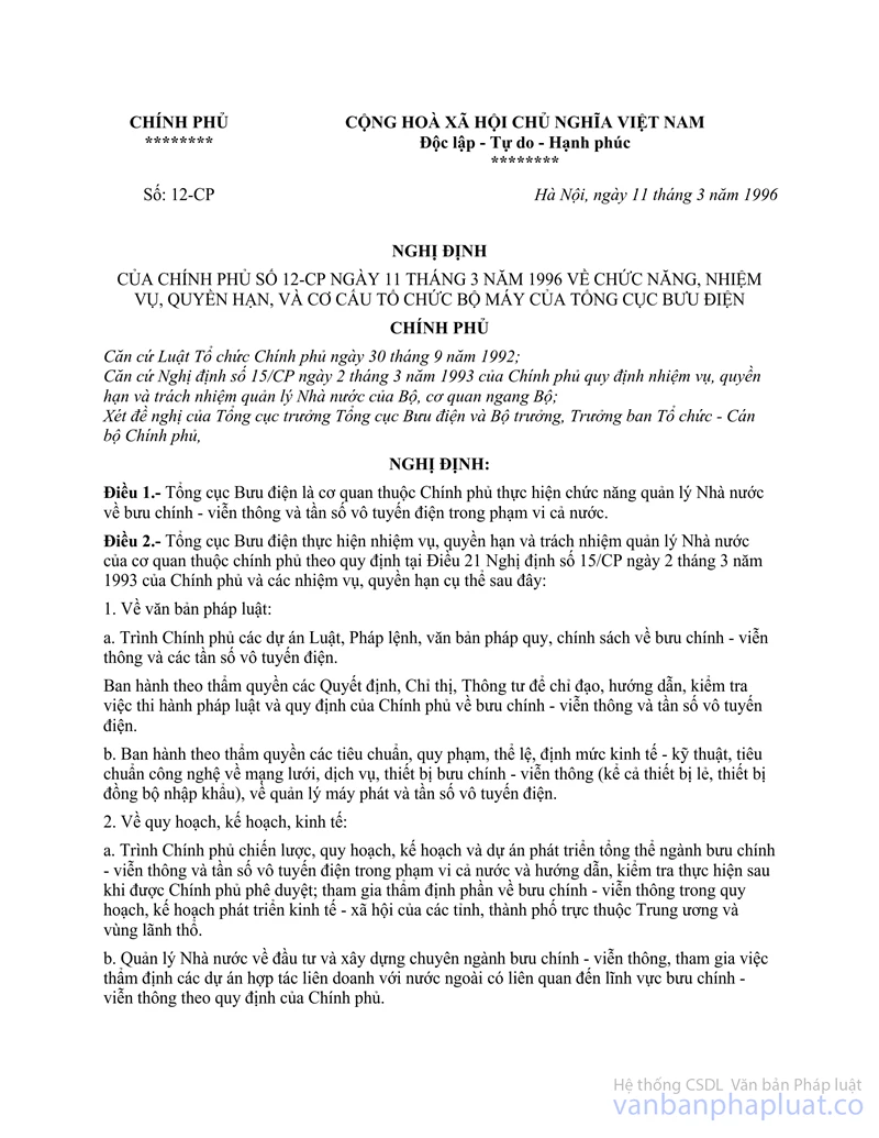
8.10 Đặc điểm tần số quá độ của máy phát
8.10.1 Định nghĩa
Đặc điểm tần số quá độ của máy phát là sự biến thiên theo thời gian của chênh lệch tần số tức thời so với tần số danh định khi bật và tắt máy.
ton: Theo phép đo mô tả ở mục 8.4.2, lúc bật máy phát được xác định khi công suất ra (đo ở cổng anten) vượt quá 0,1% công suất danh định.
t1: Khoảng thời gian bắt đầu từ ton và kết thúc tại thời điểm chỉ ra trong bảng 4.
t2: Khoảng thời gian bắt đầu từ t1 và kết thúc tại thời điểm như chỉ ra trong bảng 4.
toff: Lúc tắt máy được xác định khi công suất ra giảm xuống dưới 0,1% công suất danh định.
t3: Khoảng thời gian bắt đầu tại thời điểm như chỉ ra trong bảng 4 và kết thúc ở toff.
Bảng 4. Các khoảng thời gian
|
t1 (ms) |
5,0 |
|
t2 (ms) |
20,0 |
|
t3 (ms) |
5,0 |
8.10.2 Phương pháp đo
Hai tín hiệu được nối tới bộ phân biệt đo kiểm qua mạch phối hợp (6.2.2) như hình 3.
Đầu ra của bộ suy giảm công suất nối với bộ phân biết đo kiểm qua một đầu vào của mạch phối hợp.

Hình 3. Sơ đồ đo
Bộ tạo tín hiệu đo kiểm nối tới đầu vào thứ hai của mạch phối hợp.
Tín hiệu đo kiểm được điều chỉnh tới tần số danh định của máy phát và điều chế bởi tần số 1 kHz với độ lệch tần 25 kHz.
Mức tín hiệu đo kiểm được điều chỉnh ứng với 0,1% công suất của máy phát đo được ở đầu vào bộ phân biệt đo kiểm. Mức này được giữ không đổi trong khi đo kiểm.
Đầu ra lệch tần (fd) và lệch biên độ (ad) của bộ phân biệt đo kiểm được nối với một giải động kế tích luỹ.
Giải động kế được đặt để hiển thị kênh tương ứng với đầu vào (fd) cách tần số danh định cộng hoặc trừ chênh lệch tần số một kênh (bằng độ rộng kênh 25 kHz).
Giải động kế được đặt ở tốc độ quét 10 ms/độ chia và đặt cho lật trạng thái xảy ra ở 1 độ chia tận cùng bên trái màn hình.
Màn hình sẽ cho thấy tín hiệu đo kiểm 1 kHz liên tục.
Sau đó giải động kế được đặt để lật trạng thái kênh ứng với đầu vào lệch biên độ (ad) ở mức vào thấp rồi tăng dần lên.
Sau đó bật máy phát, không có điều chế để tạo ra xung lật trạng thái và hình ảnh trên màn hình hiển thị.
Kết quả thay đổi tỷ số công suất giữa tín hiệu đo kiểm và đầu ra máy phát sẽ tạo ra hai đường biên riêng biệt trên hình ảnh, một đường mô tả tín hiệu đo kiểm 1 kHz, còn đường kia mô tả chênh lệch tần số theo thời gian.
Tại thời điểm khi tín hiệu đo kiểm 1 kHz bị chặn hoàn toàn được coi là thời điểm ton.
Khoảng thời gian t1 và t2 như định nghĩa trong bảng 4 được dùng để xác định sự quá độ phù hợp (hình 4).
Vẫn bật máy phát.
Giải động kế được đặt để chuyển trạng thái kênh tương ứng với đầu vào lệch biên độ (ad) ở mức vào cao, giảm dần và đặt sao cho lật trạng thái xảy ở một độ chia tận cùng biên phải màn hình.
Sau đó tắt máy.
Thời điểm khi tín hiệu đo kiểm 1 kHz bắt đầu tăng vọt được coi là toff.
Thời gian t3 như định nghĩa trong bảng 4 được sử dụng để xác định sự quá độ phù hợp (hình 4).
Phép đo kiểm này chỉ thực hiện trên một kênh (6.6).
8.10.3 Giới hạn
Kết quả đo là sự lệch tần theo thời gian.
Trong các khoảng thời gian t1 và t2, lệch tần số không được lớn hơn giá trị cho ở 8.10.1.
Độ lệch tần số, sau khi kết thúc t2 phải nằm trong giới hạn sai số tần số, xem mục 8.1.
Trong khoảng thời gian t3, lệch tần số không được lớn hơn giá trị cho ở 8.10.1.
Trước lúc bắt đầu t3, lệch tần số phải nằm trong giới hạn sai số tần số, xem mục 8.1.
8.11 Phát xạ tạp dẫn tới anten
8.11.1 Định nghĩa
Phát xạ tạp dẫn tới anten là phát xạ trên các tần số nằm ngoài băng thông cần thiết. Mức của phát xạ này có thể giảm bớt mà không làm ảnh hưởng đến việc truyền dẫn thông tin tương ứng. Phát xạ này gồm phát xạ hài, phát xạ ký sinh, thành phần xuyên điều chế và thành phần đổi tần nhưng không gồm các phát xạ ngoài băng.
|

Hình 4: Đặc điểm tần số quá độ của máy phát
8.11.2 Phương pháp đo
Phát xạ tạp được đo với một máy phát chưa điều chế và được nối với một anten giả (6.5).
Phép đo kiểm được thực hiện trên dải 9 kHz tới 2 GHz, ngoại trừ kênh máy phát đang hoạt động và các kênh lân cận của nó.
Các phép đo cho từng phát xạ tạp được thực hiện nhờ một thiết bị đo vô tuyến có dò tìm hoặc một máy phân tích phổ.
8.11.3 Giới hạn
Công suất phát xạ tạp trên mỗi tần số không vượt quá 0,25 mW.
9. Máy thu
9.1 Công suất ra âm tần biểu kiến và méo hài
9.1.1 Định nghĩa
Méo hài tại đầu ra máy thu là tỷ số (tính theo phần trăm) của tổng điện áp rms các thành phần hài của tần số âm tần điều chế và tổng điện áp rms của tín hiệu máy thu đưa ra.
Công suất ra âm tần biểu kiến là giá trị nhà sản xuất công bố và là công suất cực đại có thể của máy thu mà vẫn thoả mãn mọi yêu cầu của bản tiêu chuẩn này.
9.1.2 Phương pháp đo
Các tín hiệu có các mức +60 dBmV và +100 dBmV ở tần số mang bằng tần số danh định của máy thu theo các điều kiện 6.2.2.
Đối với mỗi phép đo, điều khiển âm lượng phải đặt sao cho để
đạt (trên tải trở tương ứng tải khai thác của máy thu) công suất ra âm tần biểu
kiến (9.1.1). Nhà sản xuất phải công bố giá trị tải này. Điều chế lần lượt ở
các tần số 300Hz, 500Hz và
1 kHz với chỉ số điều chế không đổi là 3. Méo hài và công suất ra ầm tần phải
đo ở tất cả các tần số xác định ở trên.
Ở điều kiện tới hạn (5.4.1 và 5.4.2 áp dụng đồng thời), việc đo kiểm phải thực hiện ở tần số danh định thu và tần số danh định thu ±1,5 kHz. Đối với các đo kiểm này, tần số điều chế phải là 1 kHz và lệch tần số phải là ±3 kHz.
Phương pháp đo chỉ thực hiện trên một kênh (6.6).
9.1.3 Giới hạn
Công suất ra âm tần biểu kiến ít nhất phải là:
- 200 mW ở loa.
- 1 mW ở tai nghe nếu có trang bị
Méo hài không vượt quá 10%.
9.2 Đáp ứng tần số âm tần
9.2.1 Định nghĩa
Đáp ứng tần số âm tần là sự biến đổi mức ra tần số âm tần máy thu như hàm của tần số điều chế của tín hiệu tần số vô tuyến với độ lệch không đổi cấp tới đầu vào của nó.
9.2.2 Phương pháp đo
Tín hiệu đo kiểm (mức +60 dBmV, tần số mang bằng tần số danh định của máy thu và được điều chế bằng điều chế đo kiểm bình phương 6.4) đưa tới cổng anten máy thu ở điều kiện 6.2.2.
Điều khiển công suất máy thu đặt sao cho để tạo ra nếu công suất bằng 50% công suất ra biểu kiến (9.1). Sự thiết lập này phải giữ không đổi trong suốt quá trình đo kiểm.
Sau đó độ lệch tần số phải giảm đến 1 kHz và đầu ra âm tần là điểm tham chiếu trên hình 5 (1 kHz tương ứng với 0 dB).
Giữ cho độ lệch không đổi, thay đổi tần số điều chế giữa 300 Hz và 3 kHz, đo mức đầu ra.
Phép đo được lặp lại với tín hiệu đo kiểm ở các tần số bằng tần số danh định máy thu ±1,5 kHz.
Phép đo chỉ thực hiện trên một kênh (6.6).
9.2.3 Giới hạn
Đáp ứng âm tần không lệch hơn +1 dB hoặc -3 dB khỏi đường
đặc tính có mức ra là một hàm của tần số âm tần, hàm này giảm 6 dB/octave và đi
qua điểm đo ở
1 kHz (hình 5).
|

Hình 5: Đáp ứng âm tần của máy thu
9.3 Độ nhạy khả dụng cực đại
9.3.1 Định nghĩa
Độ nhạy khả dụng cực đại của máy thu là mức tín hiệu nhỏ nhất ở tần số danh định của máy thu mà khi đưa tới cổng anten của máy thu với điều chế đo kiểm bình thường sẽ tạo ra:
+ Trong mọi trường hợp, công suất ra âm tần cực đại bằng 50% công suất ra biểu kiến, và
+ Tỷ số SINAD đo ở đầu ra máy thu là 20 dB (Khuyến nghị P.53 ITU-T [4]).
9.3.2 Phương pháp đo
Tín hiệu đo kiểm (có tần số mang bằng tần số danh định máy thu và được điều chế bởi điều chế đo kiểm bình thường) đưa tới cổng anten máy thu. Tải tần số âm tần và thiết bị đo tỷ số SINAD (9.3.1) nối tới đầu ra máy thu.
Mức tín hiệu đo kiểm được điều chỉnh đến khi đạt SINAD bằng 20 dB, sử dụng máy đo tạp âm thoại và điều khiển công suất âm tần máy thu để tạo công suất bằng 50% công suất ra biểu kiến. Mức tín hiệu đo kiểm ở cổng anten là giá trị độ nhạy khả dụng cực đại.
Các phép đo được thực hiện cả ở điều kiện đo kiểm bình thường (6.4) và điều kiện đo kiểm tới hạn (5.4.1 và 5.4.2 áp dụng đồng thời).
Khi đo độ nhạy ở điều kiện đo kiểm tới hạn, cho phép công suất ra máy thu (tương ứng 50% công suất ra biểu kiến) biến đổi trong khoảng ±3 dB.
9.3.3 Giới hạn
· Ở điều kiện đo kiểm bình thường, độ nhạy khả dụng cực đại không lớn hơn +6 dBmV.
· Ở
điều kiện đo kiểm tới hạn, độ nhạy khả dụng cực đại không lớn hơn
+12 dBmV.
9.4 Độ triệt nhiễu cùng kênh
9.4.1 Định nghĩa
Độ triệt nhiễu cùng kênh là khả năng máy thu thu được tín hiệu điều chế mong muốn khi có tín hiệu không mong muốn, cả hai tín hiệu này đều ở tần số danh định của máy thu.
9.4.2 Phương pháp đo
Hai tín hiệu vào được nối với cổng anten máy thu qua mạch phối hợp (6.2.2). Tín hiệu điều chế mong muốn phải có điều chế đo kiểm bình thường (6.4). Tín hiệu không mong muốn được điều chế bằng 400 Hz với độ lệch tần 3 kHz. Cả hai tín hiệu vào được đặt ở tần số danh định của máy thu cần đo kiểm. Phép đo được lặp lại với sự thay đổi tần số tín hiệu không mong muốn ±3 kHz.
Mức tín hiệu vào mong muốn đặt ở giá trị ứng với độ nhạy khả dụng cực đại. Sau đó biên độ của tín hiệu vào không mong muốn được điều chỉnh đến khi tỷ số SINAD ở đầu ra máy thu giảm xuống tới 14 dB.
Tỷ số triệt nhiễu cùng kênh được biểu thị bằng tỷ số (dB) của mức tín hiệu không mong muốn trên mức tín hiệu mong muốn ở cổng anten máy thu mà với nó một lượng giảm cụ thể tỷ số SINAD như trên (giảm xuống 14 dB) xảy ra.
Phép đo này chỉ thực hiện trên một kênh (6.6).
9.4.3 Giới hạn
Tỷ số triệt nhiễu cùng kênh phải ở giữa -10 dB và 0 dB.
9.5 Độ chọn lọc kênh lân cận
9.5.1 Định nghĩa
Độ chọn lọc kênh lân cận là khả năng của máy thu thu được tín hiệu điều chế mong muốn khi có tín hiệu không mong muốn có tần số lệch với tần số tín hiệu mong muốn là 25 kHz.
9.5.2 Phương pháp đo
Hai tín hiệu vào được đưa tới cổng anten máy thu qua mạch
phối hợp (6.2.2). Tín hiệu mong muốn ở tần số danh định của máy thu và có điều
chế đo kiểm bình thường. Tín hiệu không mong muốn được điều chế bởi 400 Hz với
độ lệch tần
±3 kHz và ở tần số cao hơn tần số tín
hiệu mong muốn là 25 kHz.
Mức tín hiệu vào mong muốn được đặt bằng giá trị tương ứng với độ nhạy khả dụng cực đại. Sau đó biên độ tín hiệu vào không mong muốn được điều chỉnh đến khi tỷ số SINAD ở đầu ra máy thu giảm tới 14 dB. Phép đo được lặp lại với tín hiệu không mong muốn ở tần số thấp hơn tần số tín hiệu mong muốn là 25 kHz.
Độ chọn lọc kênh lân cận được biểu diễn bằng giá trị nhỏ nhất trong hai tỷ số (tính bằng dB) của mức tín hiệu không mong muốn đối với kênh lân cận trên và dưới trên mức tín hiệu mong muốn.
9.5.3 Giới hạn
Độ chọn lọc kênh lân cận không nhỏ hơn 70 dB.
9.6 Triệt đáp ứng tạp
9.6.1 Định nghĩa
Triệt đáp ứng tạp là khả năng máy thu phân biệt giữa tín hiệu mong muốn ở tần số danh định và tín hiệu không mong muốn ở tần số bất kỳ khác có thu được đáp ứng.
9.6.2 Phương pháp đo
Hai tín hiệu vào được đưa tới cổng anten máy thu qua mạch phối hợp (6.2.2). Tín hiệu mong muốn ở tần số danh định máy thu và được điều chế với điều chế đo kiểm bình thường (6.4).
Tín hiệu không mong muốn được điều chế bởi 400 Hz với độ lệch tần 3 kHz.
Mức tín hiệu vào mong muốn được đặt ở giá trị tương ứng với
độ nhạy khả dụng cực đại. Biên độ của tín hiệu vào không mong muốn điều chỉnh
tới
+86 dBmV. Sau đó tần số được thay đổi từng
bước (không quá 5 kHz) trong dải từ 100 kHz đến 2000 MHz.
Ở tần số bất kỳ nào thu được đáp ứng, mức vào sẽ được điều chỉnh đến khi tỷ số SINAD giảm tới 14 dB.
Triệt đáp ứng tạp biểu thị bởi tỷ số (dB) giữa tín hiệu không mong muốn và tín hiệu mong muốn ở cổng anten máy thu khi mức giảm cụ thể tỷ số SINAD như trên (giảm tới 14 dB) thu được.
Phép đo chỉ thực hiện ở một kênh (6.6).
9.6.3 Giới hạn
Ở tần số bất kỳ cách tần số danh định máy thu hơn 25 kHz. Triệt đáp ứng tạp không nhỏ hơn 70 dB.
9.7 Đáp ứng xuyên điều chế
9.7.1 Định nghĩa
Đáp ứng xuyên điều chế là khả năng của máy thu thu tín hiệu điều chế mong muốn khi có hai hay nhiều tín hiệu không mong muốn có mối liên quan tần số đặc biệt với tần số tín hiệu mong muốn, đảm bảo mức suy giảm chất lượng thấp hơn mức đã cho.
9.7.2 Phương pháp đo
Nối ba máy phát A, B, C tới cổng anten máy thu qua mạch phối hợp (6.2.2). Tín hiệu mong muốn từ máy phát A được đặt ở tần số danh định máy thu và có điều chế đo kiểm bình thường (6.4). Tín hiệu không mong muốn từ máy phát B không được điều chế và chỉnh tới tần số lớn hơn tần số danh định máy thu 50 kHz. Tín hiệu không mong muốn thứ hai từ máy phát C được điều chế bằng 400 Hz với lệch tần 3 kHz và được điều chỉnh tới tần số lớn hơn tần số danh định máy thu 100 kHz.
Đặt tín hiệu vào mong muốn ứng với độ nhạy khả dụng cực đại (9.3). Biên độ của hai tín hiệu không mong muốn giữ bằng nhau và được điều chỉnh đến khi tỷ số SINAD ở cổng ra máy thu giảm xuống tới 14 dB. Tần số máy phát B được điều chỉnh để có được sự giảm cấp cực đại của tỷ số SINAD. Mức của hai tín hiệu không mong muốn được điều chỉnh lại để phục hồi tỷ số SINAD bằng 14 dB. Tỷ số đáp ứng xuyên điều chế được biểu diễn bằng tỷ số (dB) giữa hai tín hiệu không mong muốn và tín hiệu mong muốn ở cổng anten máy thu, khi nhận được một lượng giảm tỷ số SINAD như trên.
Phép đo được lặp lại với tín hiệu từ máy phát B ở tần số cao hơn tần số tín hiệu mong muốn là 25 kHz và tín hiệu không mong muốn từ máy phát C ở tần số cao hơn tần số tín hiệu mong muốn là 50 kHz.
Các phép đo trên được lặp lại với các tín hiệu không mong muốn có tần số thấp hơn tần số danh định máy thu một khoảng như trên.
9.7.3 Giới hạn
Tỷ số đáp ứng điều chế phải lớn hơn 68 dB.
9.8 Nghẹt
9.8.1 Định nghĩa
Nghẹt là sự thay đổi (thường là giảm) công suất ra âm tần mong muốn của máy thu hoặc giảm tỷ số SINAD do một tín hiệu không mong muốn ở tần số khác.
9.8.2 Phương pháp đo
Hai tín hiệu vào được đưa tới máy thu qua mạch phối hợp (6.2.2). Tín hiệu điều chế mong muốn ở tần số danh định máy thu với điều chế đo kiểm bình thường (6.4). Lúc đầu tín hiệu không mong muốn được ngắt và tín hiệu mong muốn được đặt ở giá trị tương ứng với độ nhạy khả dụng cực đại (9.3).
Công suất ra âm tần của tín hiệu mong muốn được điều chỉnh ở chỗ có thể, bằng 50% công suất ra âm tần biểu kiến và trong trường hợp có điều khiển âm lượng theo bước, ở bước đầu tiên phải tạo ra công suất ra âm tần ít nhất bằng 50% công suất ra âm tần biểu kiến. Tín hiệu không mong muốn không điều chế ở các tần số ±1 MHz, ±2 MHz, ±5 MHz, ±10 MHz ứng với tần số danh định máy thu.
Mức vào của tín hiệu không mong muốn (ở mọi tần số trong phạm vi xác định) được điều chỉnh sao cho:
- Mức ra của tín hiệu mong muốn giảm 3 dB, hoặc
- Tỷ số SINAD ở đầu ra âm tần máy thu giảm xuống bằng 14 dB, không kể điều kiện nào xảy ra trước. Mức này phải được ghi lại.
9.8.3 Giới hạn
Mức nghẹt ở mọi tần số trong một giải xác định không nhỏ hơn 90dBmV, ngoại trừ ở các tần số có đáp ứng tạp.
9.9 Phát xạ tạp dẫn tới anten
9.9.1 Định nghĩa
Phát xạ tạp dẫn tới anten là các thành phần ở tần số bất kỳ sinh ra trong máy thu và được bức xạ bởi anten máy thu.
Mức phát xạ tạp được đo bằng mức công suất của nó ở đường truyền dẫn hay anten.
9.9.2 Phương pháp đo
Phát xạ tạp được đo bằng mức công suất của tín hiệu bất kỳ ở cổng anten máy thu. Cổng anten máy thu nối tới bộ phân tích phổ hay vôn kế chọn lọc có trở kháng vào 50W và máy thu được bật.
Nếu thiết bị tách sóng (dò) không chịu đo theo giá trị đầu vào công suất, mức của thành phần tách sóng bất kỳ được xác định theo phương pháp thay thế dùng bộ tạo tín hiệu.
Các phép đo được mở rộng trong giải tần từ 9 kHz đến 2 GHz.
9.9.3 Giới hạn
Công suất của thành phần tạp bất kỳ giữa 9 kHz và 2 GHz không được lớn hơn 2 nW.
PHỤ LỤC A
(Quy định)
ĐO CÔNG SUẤT KÊNH LÂN CẬN
Phụ lục mô tả phương pháp đo công suất kênh lân cận dùng máy thu đo công suất.
Chỉ tiêu kỹ thuật của máy thu đo công suất được cho trong mục A.2.
A.1. Phương pháp đo
Tuân theo thủ tục sau:
a) Máy phát phải hoạt động ở công suất sóng mang như trong mục 8.2. Cổng anten của máy phát được nối tới đầu vào máy thu đo công suất bằng một đầu nối sao cho trở kháng tác động tới máy phát là 50 W và mức ở đầu vào máy thu đo công suất là phù hợp;
b) Với máy phát chưa điều chế, dò máy thu đo công suất sao cho thu được đáp ứng cực đại. Đây là điểm đáp ứng 0 dB. Giá trị đặt bộ suy hao máy thu đo công suất và chỉ số công suất kế được ghi lại.
Phép đo có thể được thực hiện với máy phát điều chế với điều chế đo kiểm thông thường, khi đó nội dung này phải được ghi trong kết quả đo kiểm;
c) Dò máy thu đo công suất ra xa sóng mang sao cho đáp ứng -6 dB của máy thu đo công suất gần nhất với tần số sóng mang của máy phát được phân định ở tần số cách tần số sóng mang danh định 17 kHz;
d) Máy phát được điều chế ở 1,25 kHz và mức 20 dB cao hơn mức cần thiết để có độ lệch ±3 kHz;
e) Bộ suy hao khả biến của máy thu đo được điều chỉnh để đạt được cùng chỉ số của công suất kế ở bước (b) hoặc có tỷ lệ đã biết liên quan đến chỉ số đó;
f) Tỷ số công suất kênh lân cận trên công suất sóng mang là sự chênh lệch giữa các giá trị đặt bộ suy hao trong bước (b) và (e) và chỉ số của công suất kế;
g) Phép đo được lặp lại khi dò máy thu đo công suất tới phía sườn kia của sóng mang.
A.2. Chỉ tiêu của máy thu đo công suất
Máy thu đo công suất gồm một bộ trộn, bộ lọc IF, bộ dao động ký, bộ khuếch đại, bộ suy hao khả biến và bộ chỉ thị giá trị rms. Thay cho bộ suy hao khả biến có bộ chỉ thị giá trị rms, có thể dùng một vôn kế rms chuẩn thu dB. Đặc tính kỹ thuật của máy thu đo công suất được đưa ra dưới đây.
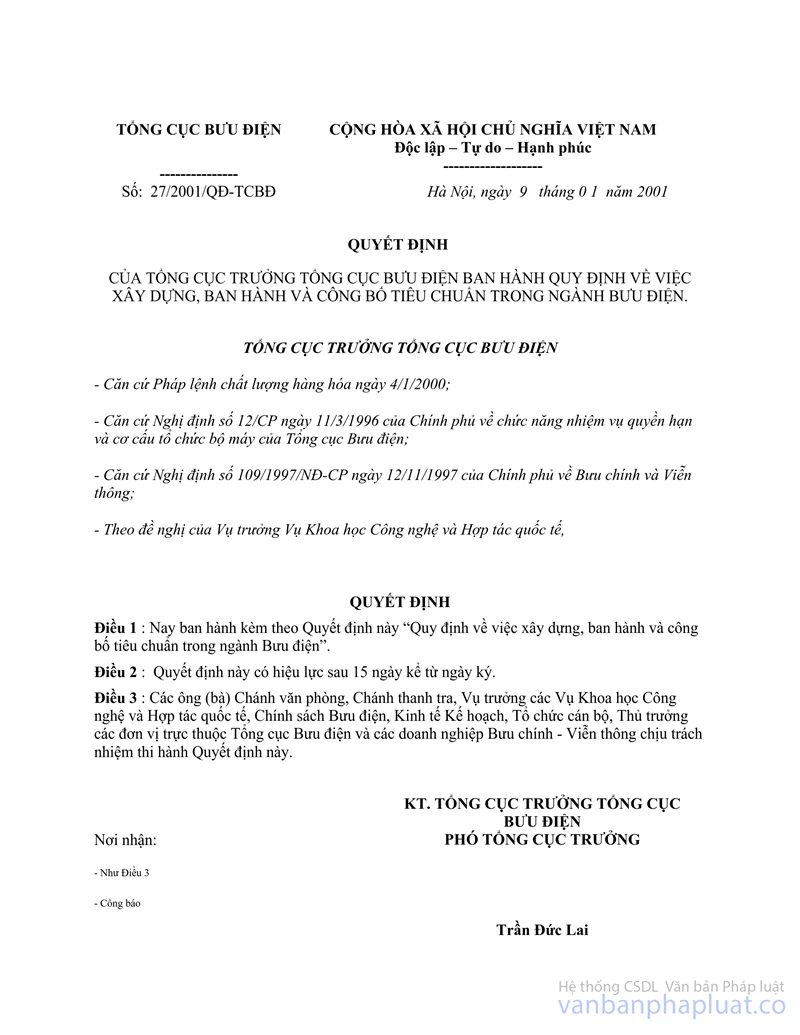
A.2.1 Bộ lọc IF
Phải nằm trong giới hạn các đặc tính chọn lọc sau (xem hình A.1).
Hình A.1
Đặc tính chọn lọc này (xem bảng A.1) phải giữ khoảng cách tần số so với tần số trung tâm danh định của kênh lân cận như sau:
Bảng A.1. Đặc tính chọn lọc
|
Khoảng cách tần số của đường cong bộ lọc so với tần số trung tâm danh định của kênh lân cận (kHz) |
|||
|
D1 |
D2 |
D3 |
D4 |
|
5 |
8,0 |
9,25 |
13,25 |
Các điểm suy hao lại gần sóng mang (bảng A.2) không được vượt quá sai số cho trong bảng A.2
Bảng A.2. Các điểm suy hao lại gần với sóng mang
|
Dải sai số (kHz) |
|||
|
D1 |
D2 |
D3 |
D4 |
|
+3,1 |
±0,1 |
-1,35 |
-5,35 |
Các điểm suy hao (xa khỏi sóng mang (bảng A.3) không được vượt quá sai số cho trong bảng A.3.
Bảng A.3. Các điểm suy hao xa khỏi sóng mang
|
Dải sai số (kHz) |
|||
|
D1 |
D2 |
D3 |
D4 |
|
±3,5 |
±3,5 |
±3,5 |
+3,5 -7,5 |
Suy hao nhỏ nhất của bộ lọc bên ngoài các điểm suy hao 90 dB phải bằng hoặc lớn hơn 90 dB.
A.2.2. Bộ chỉ thị suy hao
Đèn chỉ thị suy hao phải có dải tối thiểu là 80 dB và độ phân giải chính xác đến 1 dB. Khuyến nghị suy hao 90 dB hoặc hơn để hướng tới những qui định trong tương lai.
A.2.3. Bộ chỉ thị giá trị RMS
Dụng cụ này phải chỉ thị chính xác tín hiệu không phải hình sin với hệ số đỉnh là 10.
A.2.4. Dao động ký và bộ khuếch đại
Dao động ký và bộ khuếch đại phải được thiết kế theo cách mà phép đo công suất kênh lân cận của máy phát không điều chế tạp âm thấp đem lại giá trị đo được -90 dB.
TCN 68 - 206: 2001
UHF RADIO TELEPHONE
TECHNICAL REQUIREMENTS
FOREWORD
The technical standard TCN 68 - 206: 2001 "UHF radio telephone - Technical requirements" is based on the ETS 300 720 of the European Telecommunications Standards Institute (ETSI).
The technical standard TCN 68 - 206: 2001 is drafted by Research Institute of Posts and telecommunications.
The technical standard TCN 68 - 206: 2001 is issued following the Decision No 1060/2001/QĐ-TCBĐ of the Secretary General of the Department General of Posts and Telecommunications dated 21/12/2001.
An unofficial translation of the technical standard TCN 68 - 206: 2001 into English is edited. In cases of interpretation disputes, Vietnamese version is applied.
SCIENCE-TECHNOLOGY & INTERNATIONAL COOPERATION DEPARTMENT
|
DEPARTMENT GENERAL |
THE SOCIALIST REPUBLIC OF VIETNAM |
|
No: 1060/2001/QĐ-TCBĐ |
Hanoi, 21 December 2001 |
DECISION OF SECRETARY GENERAL
ISSUING THE DGPT STANDARD
SECRETARY GENERAL
OF DEPARTMENT GENERAL OF POSTS AND TELECOMMUNICATIONS
Pursuant to the Ordinance of January 04, 2000 of Standing
Committee of National Assembly on Quality of goods;
Pursuant to the Government's Decree No. 12/CP of March 11, 1996 on The
functions, responsibilities, obligations and organizational structures of
Department General of Posts and Telecommunications;
Pursuant to the Government's Decree No. 109/1997/NĐ-CP of November 12, 1996 on
Posts and Telecommunications;
Pursuant to the Decision No 27/2001/QĐ-TCBĐ of Department General of Posts and
Telecommunications of January 09, 2001 on establishing, issuing and adopting
standards;
At the proposal of the Director General of Science - Technology and
International Cooperation Department,
DECIDES
Article 1.- To issue together with this Decision the DGPT standard “UHF radio telephone - Technical requirements” - Code: TCN 68 - 206: 2001.
Article 2.- The DGPT standard mentioned in the Article 1 takes effect 15 (fifteen) days from after signing of this Decision.
Article 3.- The Heads of Administrative Bureau, Departments, Agencies attached to DGPT and Heads of Posts and Telecommunications Corporations shall have to implement this Decision.
|
|
FOR THE SECRETARY GENERAL OF DEPARTMENT
GENERAL |
UHF RADIO TELEPHONE
TECHNICAL REQUIREMENTS
(Issued together with the Decision No 1060/2001/QĐ-TCBĐ of the Secretary General of DGP T of December 21, 2001)
1. Scope
This standard specifies the minimum technical characteristics required for UHF radio equipment operating in the Global Maritime Distress and Safety System (GMDSS).
This technical standard is used as the basic for type approval of UHF radio telephone.
2. Normative references
[1]. ETS 300 720, "Radio Equipment and System (RES); Technical characteristics and methods of measurement for UHF on-board communications systems and equipment", March 1997, ETSI.
[2]. ITU Radio Regulation, appendix 20: "Characteristics of equipment used for on-board communication in the bands between 450 and 479 MHz".
[3]. ETR 028:"Radio Equipment and System (RES); Uncertainties in the measurement of mobile radio equipment characteristics ".
[4]. Recommendation ITU-TP.53 (1998): "Psophometer (apparatus for the objective measurement of circuit noise )".
[5]. Recommendation ISO 694: "Positioning of magnetic compasses in ships".
3. Definitions, abbreviations and symbols
3.1 Definition
Modulation index: The ratio between the frequency deviation and the modulation frequency.
3.2 Abbreviations
- emf: electro-motive force
- ERP: effective radiated power
- SINAD: signal + noise + distortion/noise + distortion
- rms: root mean square
3.3 Symbols
dBA acoustic level in dB relative to 2 x10⁻⁵ Pa.
4. General requirements
4.1 Construction
The mechanical and electrical construction and finish of the equipment shall conform in all respects to good engineering practice and the equipment shall be suitable for use on board ships. The equipment's colour shall be neither orange nor yellow.
4.2 Frequencies
The equipment shall operate either on single-frequency or two-frequency simplex channels on frequencies:
Table 1: Single frequency simplex channels
|
Channel designator |
Frequency |
|
Channel A |
467,525 MHz |
|
Channel B |
467,550 MHz |
|
Channel C |
467,575 MHz |
|
Channel D |
457,525 MHz |
|
Channel E |
457,550 MHz |
|
Channel F |
457,575 MHz |
Table 2: Two-frequency simplex channels for use with repeater only
|
Channel designator |
Transmit frequency |
Receive frequency |
|
Channel G |
467.525 MHz |
457.525 MHz |
|
Channel H |
467.550 MHz |
457.550 MHz |
|
Channel J |
467.575 MHz |
457.575 MHz |
Independent selection of transmitting and receiving frequencies shall not be possible.
The equipment shall be fitted with at least one single-frequency simplex channel, the frequency of which shall be 457.525 MHz.
It shall not be possible to transmit during channel-switching operations.
4.3 Controls
The equipment shall have the following controls:
- A channel selector which shall indicate the designator of the channel to which the equipment is set;
- On/off switch for the equipment with visual indication that the equipment is switched on;
- A manual non-locking, push-to-talk switch to operate the transmitter;
- An audio-frequency power volume control.
4.4 Switching time
The channel switching arrangements shall be such that the time necessary to change over from using one of the channels to using any other channel does not exceed 5 seconds.
The time necessary to change over from transmission to reception and vice versa, shall not exceed 0.3 seconds.
4.5 Safety precautions
Provision shall be made for protecting equipment from the effects of excessive current or voltage. Means shall be incorporated to prevent reversal of polarity of the battery power supply.
Equipment with an antenna socket shall not be damaged by the effect of open-circuit or short-circuit of the antenna socket for a period of at least 5 minutes.
The manufacturer shall declare the compass safe distance according to Recommendation ISO 694 [5].
4.6 Class of emission and modulation characteristics
The equipment shall use phase modulation, G3E (frequency modulation with a pre-emphasis of 6 dB/octave).
The equipment shall be designed to operate with a channel spacing of 25 kHz.
4.7 Battery
The battery may be an integral part of the equipment.
Primary and/or secondary batteries may be used.
If the equipment is fitted with secondary batteries, a suitable battery charger shall be recommended by the manufacturer.
4.8 Loudspeaker and microphone
The equipment shall be provided with a microphone and a loudspeaker which may be combined.
In the transmit condition the output of the receiver shall be muted.
4.9 Labelling
All controls shall be clearly labelled. The labelling shall include: the name of the manufacturer and his trade mark; the type number and serial number of the equipment; and the compass safe distance.
4.10 Equipment documentation
Adequate technical and operational documentation shall be supplied with the equipment.
5. Test conditions, power sources and ambient temperatures
5.1 Normal and extreme test conditions
Tests shall be made under normal test conditions and also, where stated, under extreme test conditions.
5.2 Test power source
Unless otherwise stated, the battery of the equipment shall be replaced by a test power source capable of producing normal and extreme test voltages as specified in subclauses 5.3.2 and 5.4.2.
The voltage of the power source shall be measured at the input terminal of the equipment.
During testing, the power source voltage shall be maintained within a tolerance of ±3 % relative to the voltage level at the beginning of each test.
5.3 Normal test conditions
5.3.1 Normal temperature and humidity
The normal temperature and humidity conditions for tests shall be a combination of temperature and humidity within the following limits:
- Temperature: +15oC to +35oC;
- Relative humidity: 20% to 75%.
5.3.2 Normal test voltage
The normal test voltage shall be the nominal voltage of the battery as declared by the manufacturer.
5.4 Extreme test conditions
5.4.1 Extreme temperatures
5.4.1.1 Upper extreme temperature
Tests at the upper extreme temperature shall be made at +55oC.
5.4.1.2 Lower extreme temperature
Tests at the lower extreme temperature shall be made at -20oC.
5.4.2 Extreme test power supply values
5.4.2.1 Upper extreme test voltage
The upper extreme test voltage shall be declared by the manufacturer and shall not be lower than the following:
- When using primary batteries, the voltage corresponding to the voltage that a fresh battery gives at the upper extreme temperature when loaded with a load equal to that of the equipment in the muted receive condition;
- When using secondary batteries, the voltage corresponding to the voltage that a fully charged battery gives at the upper extreme temperature when loaded with a load equal to that of the equipment in the muted receive condition.
5.4.2.2 Lower extreme test voltage
The lower extreme test voltage shall be declared by the manufacturer and shall not be higher than the following:
- When using primary batteries, 0.85 times the voltage that a fresh battery gives at the lower extreme temperature when loaded with a load equal to that of the equipment in the muted receive condition;
- When using secondary batteries, 0.85 times the voltage that a fully charged battery gives at the lower extreme temperature when loaded with a load equal to that of the equipment in the muted receive condition.
5.5 Procedure for tests at extreme temperatures
The equipment shall be placed in the test chamber at normal temperature. The maximum rate if rising or reducing the temperature of the chamber shall be 1oC/minute. The equipment shall be switched off during the temperature-stabilising periods.
Before conducting tests at extreme temperatures, the equipment in the test chamber shall have reached thermal equilibrium and be subjected to the extreme temperature for a period of 10 to 16 hours.
For tests at the lower extreme temperature, the equipment shall then be switched on to the standby or receive condition for one minute, after which the relevant tests shall be performed.
The temperature of the chamber shall be maintained at the extreme temperatures for the whole duration of the performance tests.
At the end of the test, and with the equipment still in the chamber, the chamber shall be brought to room temperature in not less than one hour. The equipment shall then be exposed to normal room temperature and humidity for not less than three hours or until moisture has dispersed, whichever is the longer, before the next test is carried out. Alternatively, observing the same precautions, the equipment may be returned directly to the conditions required for the start of the next tests.
6. General conditions of measurement
6.1 Test connections
For the purpose of testing, suitable connections to the following test points shall be made available:
- The antenna terminal (for 50 W connection);
- The transmitter audio input(s);
- The receiver audio output(s);
- The push-to-talk switch;
- The battery terminals for test power source connections.
6.2 Arrangements for test signals
6.2.1 Test signals applied to the transmitter input
For the purpose of tests, the transmitter internal microphone shall be disconnected and an audio frequency signal generator shall be applied to the transmitter audio input terminals.
6.2.2 Test signals applied to the antenna terminal
Test signal generators shall be connected to the antenna terminal in such a way that the impedance presented to the receiver input is 50W, irrespective of whether one or more test signals are applied simultaneously.
The levels of the test signals shall be expressed in terms of the emf.
The effects of any intermodulation product and noise product in the test signal generators should be negligible.
The nominal frequency of the receiver is the carrier frequency of the selected channel.
6.3 Receiver mute or squelch facility
Unless otherwise specified, the receiver squelch facility shall be made inoperative for the duration of the tests.
6.4 Normal test modulation
For normal test modulation, the modulation frequency shall be 1 kHz and the frequency deviation shall be ±3 kHz.
6.5 Artificial antenna
When tests are conducted with an artificial antenna, this shall be a 50 W non-reactive, non-radiating load.
6.6 Test channels
For equipment operating in both the 457 MHz and 467 MHz bands, tests shall be carried out at the highest and lowest channels within the frequency range of the equipment.
6.7 Measurement uncertainty and interpretation of the measuring results
6.7.1 Measurement uncertainty
Table 3: Absolute measurement uncertainties
|
Specifications |
Uncertainties |
|
RF frequency |
±1 x 10⁻⁷ |
|
RF power |
±0.75 dB |
|
Maximum frequency deviation: |
|
|
- within 300 Hz to 6 kHz of audio frequency: |
±5% |
|
- within 6 kHz to 25 kHz of audio frequency: |
±3 dB |
|
Deviation limitation |
±5% |
|
Adjacent channel power |
±5 dB |
|
Audio output power |
±0.5 dB |
|
Amplitude characteristics of receiver limiter |
±1.5 dB |
|
Sensitivity at 20 dB SINAD |
±3 dB |
|
Two-signal measurement |
±4 dB |
|
Three-signal measurement |
±3 dB |
|
Radiated emission of transmitter |
±6 dB |
|
Radiated emission of receiver |
±6 dB |
|
Transmitter transient time |
±20 % |
|
Transmitter transient frequency |
±250 Hz |
6.7.2 Interpretation of the measurement results
- The measured value related to the corresponding limit will be used to decide whether an equipment meets the requirements of this standard;
- The measurement uncertainty value for the measurement of each parameter shall be included in the test report;
- The recorded value of the measurement uncertainty shall be, for each measurement, equal to or lower than the figures in table 3.
7. Environmental tests
7.1 Procedure
Environmental tests shall be carried out before any other tests of the same equipment in respect to the other requirements of this standard are performed. The tests shall be carried out in the order they appear in this standard.
Unless otherwise stated, the equipment shall be connected to an electrical power source during the periods for which it is specified that electrical tests shall be carried out. These tests shall be performed using normal test voltage and on one channel only.
7.2 Performance check
For the purpose of this standard, the term "performance check" shall be taken to mean:
- For the transmitter:
· Carrier frequency:
With the transmitter connected to an artificial antenna (see subclause 6.5), the transmitter shall be keyed without modulation. The carrier frequency shall be within ± 2.3 kHz of the nominal carrier frequency;
· Output power:
With the transmitter connected to an artificial antenna (see subclause 6.5), the transmitter shall be keyed without modulation. With the output power switch set at maximum, the output power shall be between 0.4 W and 4 W;
- For the receiver:
· Maximum usable sensitivity:
A test signal at the nominal frequency of the receiver modulated with normal test modulation (see subclause 6.4) shall be applied to the receiver input. The level of the input signal shall be adjusted until the SINAD at the output of the receiver is 20 dB and the output power is at least the rated output power (see subclause 9.1.3). The level of the input signal shall be less than +12 dBmV.
7.3 Drop test on to a hard surface
7.3.1 Definition
The immunity against the effects of dropping is the ability of the equipment to maintain the specified mechanical and electrical performance after being subjected to a series of drops on a hard wooden test surface.
7.3.2 Method of measurement
The hard wooden test surface shall consist of a piece of solid hard wood with a minimum thickness of 15 cm and a mass of 30 kg or more.
The test shall consist of a series of 6 drops, one on each surface of the equipment. During the test the equipment shall be fitted with a suitable set of batteries and antenna but it shall be switched off. The test shall be carried out under normal temperature and humidity conditions.
The height of the lowest part of the equipment under test relative to the test surface at the moment of release shall be 1 m. If the equipment is to be used with, for example, a separate microphone and/or loudspeaker, the test shall be carried out for those accessories separately.
Following the test, the equipment shall be subjected to a performance check.
7.3.3 Requirement
The requirement for the performance check shall be met.
7.4 Temperature tests
7.4.1 General
The maximum rate of raising or reducing the temperature of the chamber in which the equipment is being tested shall be 1oC/minute.
7.4.2 Dry heat
7.4.2.1 Method of measurement
The equipment shall be placed in a chamber of normal temperature. The temperature shall then be raised to and maintained at +70oC (±3oC) for a period of at least 10 hours. After this period any climatic control device provided in the equipment may be switched on and the chamber cooled to 55oC (±3oC). The cooling of the chamber shall be completed within 30 minutes. The equipment shall then be switched on and shall be kept working continuously for a period of two hours. The transmitter shall be keyed with a duty cycle of one minute transmission and four minutes reception. The equipment shall be subjected to a performance check during the two-hour period.
The temperature of the chamber shall be maintained at +55oC (±3oC) during the two-hour period.
At the end of the test, and with the equipment still in the chamber, the chamber shall be brought to room temperature in not less than one hour. The equipment shall then be exposed to normal room temperature and humidity for not less than three hours before the next test is carried out.
7.4.2.2 Requirement
The requirement for the performance check shall be met.
7.4.3 Damp heat
7.4.3.1 Method of measurement
The equipment shall be placed in a chamber at normal room temperature and humidity which, steadily, over a period three hours (±30 minutes), shall be heated from room temperature to +40oC (± 3oC) and shall during this period be brought to a relative humidity of 93% (±2%) so that excessive condensation is avoided.
30 minutes later the equipment shall be switched on, and shall then be kept working continuously for a period of two hours. The transmitter shall be keyed with a duty cycle of one minute transmission and four minutes reception.
The equipment shall be subjected to a performance check during the two-hour period. The temperature and relative humidity of the chamber shall be maintained at +40oC ± 3oC and 93% ± 2% during the two-hour, 30 minutes period.
At the end of the test, and with the equipment still in the chamber, the chamber shall be brought to room temperature in not less than one hour. The equipment shall then be exposed to normal room temperature and humidity for not less than three hours, or until moisture has dispersed, whichever is longer, before the next test is carried out.
7.4.3.2 Requirement
The requirement for the performance check shall be met.
8. Transmitter
8.1 Frequency error
8.1.1 Definition
The frequency error is the difference between the measured carrier frequency and its nominal value.
8.1.2 Method of measurement
The carrier frequency shall be measured in the absence of modulation, with the transmitter connected to an artificial antenna (see subclause 6.5).
Measurements shall be made under normal test conditions (see subclause 5.3) and under extreme test conditions (subclauses 5.4.1 and 5.4.2 applied simultaneously).
8.1.3 Limits
The frequency error shall not exceed 2,3 kHz.
8.2 Carrier power
8.2.1 Definition
The carrier power is the mean power delivered to the artificial antenna during one radio frequency cycle in the absence of modulation.
8.2.2 Method of measurement
The transmitter shall be connected to an artificial antenna (see subclause 6.5) and the power delivered to this artificial antenna shall be measured. The measurements shall be made under normal test conditions (see subclause 5.3) and under extreme test conditions (subclauses 5.4.1 and 5.4.2 applied simultaneously).
If an output power switch is fitted it shall be placed in the maximum position.
8.2.3 Limit
The carrier power shall not exceed 4 W.
8.3 Frequency deviation
8.3.1 Definition
The frequency deviation is the difference between the instantaneous frequency of the modulated radio frequency signal and the carrier frequency in the absence of modulation.
8.3.2 Maximum frequency deviation
8.3.2.1 Method of measurement
The frequency deviation shall be measured at the output with the transmitter connected to an artificial antenna (see subclause 6.5), by means of a deviation meter capable of measuring the maximum deviation, including that due to any harmonics and intermodulation products which may be generated in the transmitter.
The modulation frequency shall be varied between 100 Hz and 3 kHz. The level of this test signal shall be 20 dB above the level which produces normal test modulation (see subclause 6.4). This test shall be carried out with the output power switch set at maximum and then at minimum.
8.3.2.2 Limit
The maximum frequency deviation shall not exceed ±5 kHz.
8.3.3 Frequency deviation at modulation frequencies above 3 kHz
8.3.3.1 Method of measurement
The transmitter shall operate under normal test conditions (see subclause 5.3) connected to a load as specified in subclause 6.5. The transmitter shall be modulated by the normal test modulation (see subclause 6.4). With the input level of the modulating signal being kept constant, the modulation frequency shall be varied between 3 kHz and 25 kHz and the frequency deviation shall be measured.
8.3.3.2 Limits
For modulation frequencies between 3 kHz and 6 kHz the frequency deviation shall not exceed the frequency deviation with a modulation frequency of 3 kHz. For a modulation frequency of 6 kHz, the frequency deviation shall not exceed ±1,5 kHz, as shown in figure 1.
|
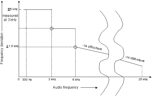
Figure 1: Frequency deviation versus audio modulation frequency
8.4 Limitation characteristics of the modulator
8.4.1 Definition
This characteristic expresses the capability of the transmitter of being modulated with a deviation approaching the maximum deviation specified in subclause 8.3.2.
8.4.2 Method of measurement
A modulating signal at a frequency of 1 kHz shall be applied to the transmitter, and its level adjusted so that the frequency deviation is ±1 kHz. The level of the modulating signal shall then be increased by 20 dB and the deviation shall again be measured.
8.4.3 Limit
The frequency deviation shall be contained between ±3.5 kHz and ±5 kHz.
8.5 Sensitivity of the modulator, including microphone
8.5.1 Definition
This sensitivity expresses the capability of the transmitter to produce sufficient modulation when an audio frequency signal corresponding to the normal mean speech level is applied to the microphone.
8.5.2 Method of measurement
An acoustic signal with a frequency of 1 kHz and a sound level of 94 dBA shall be applied to the microphone. The resulting frequency deviation shall be measured.
This test shall be carried out on one channel only.
8.5.3 Limit
The resulting frequency deviation shall be between ±1.5 kHz and ±3 kHz.
8.6 Audio frequency response
8.6.1 Definition
The audio frequency response is the frequency deviation of the transmitter a function of the modulating frequency.
8.6.2 Method of measurement
A modulating signal at a frequency of 1 kHz shall be applied to the transmitter and the deviation shall be measured at the output. The audio input level shall be adjusted so that the frequency deviation is ±1 kHz. This is the reference point in figure 2 (1 kHz corresponds to 0 dB).
The modulation frequency shall then be varied between 300 Hz and 3 kHz, with the level of the audio frequency signal being kept constant and equal to the value specified above. The test shall be carried out on one channel only (see subclause 6.6).
8.6.3 Limit
The audio frequency response shall be within +1 dB and -3 dB of a 6 dB/octave line passing through the reference point (see figure 2).
|

Figure 2: Audio frequency response
8.7 Audio frequency harmonic distortion of the emission
8.7.1 Definition
The harmonic distortion of the emission modulated by an audio frequency signal is defined as the ratio, expressed as a percentage, of the root mean square (rms) voltage of all the harmonic components of the fundamental frequency to the total rms voltage of the signal, measured after linear demodulation.
8.7.2 Method of measurement
The RF signal produced by the transmitter shall be applied via an appropriate coupling device to a linear demodulator with a de-emphasis network of 6 dB per octave.
The radio frequency signal shall be modulated successively at frequencies of 300 Hz and 1000 Hz with a constant modulation index of 3.
The distortion of the audio frequency signal shall be measured at the frequencies specified above. The test shall be carried out on one channel only (see subclause 6.6).
8.7.3 Limit
The harmonic distortion shall not exceed 10%.
8.8 Adjacent channel power
8.8.1 Definition
The adjacent channel power is that part of the total power output of a transmitter under defined conditions of modulation, which falls within a specified passband centred on the nominal frequency of either of the adjacent channels. This power is the sum of the mean power produced by the modulation, hum and noise of the transmitter.
8.8.2 Method of measurement
The output of the transmitter shall be linked to the input of a measuring device such that the impedance presented to the transmitter is 50 W.
If an output power switch is fitted it shall be placed in the maximum position.
The transmitter shall be modulated with 1 250 Hz at a level which is 20 dB higher than that required to produce ±3 kHz deviation.
The measurement shall be made in both adjacent channels.
A method of measurement using a power measuring receiver is described in annex A.
8.8.3 Limit
The adjacent channel power shall not exceed a value of 70 dB below the carrier power of the transmitter without any need to be below 0.2 mW.
8.9 Residual modulation of the transmitter
8.9.1 Definition
The residual modulation of the transmitter is the ratio, in dB, of the demodulated RF signal in the absence of wanted modulation, to the demodulated RF signal produced when the normal test modulation is applied.
8.9.2 Method of measurement
The normal test modulation defined in subclause 6.4 shall be applied to the transmitter. The high frequency signal produced by the transmitter shall be applied, via an appropriate coupling device, to a linear demodulator with a de-emphasis network of 6 dB per octave. The time constant of this de-emphasis network shall be at least 750 ms.
Precautions shall be taken to avoid the effects of emphasizing the low audio frequencies produced by internal noise.
The signal shall be measured at the demodulator output using a rms voltmeter.
The modulation shall then be switched off and the level of the residual audio frequency signal at the output shall be measured again.
The test shall be carried out on one channel only (see subclause 6.6).
8.9.3 Limit
The residual modulation shall not exceed -40 dB.
8.10 Transient frequency behaviour of the transmitter
8.10.1 Definition
The transient frequency behaviour of the transmitter is the variation in time of the transmitter frequency difference from the nominal frequency of the transmitter when the RF output power is switched on and off.
ton: according to the method of measurement described in subclause 8.10.2 the switch-on instant ton of a transmitter is defined by the condition when the output power, measured at the antenna port, exceeds 0.1% of the nominal power;
t1: period of time starting at ton and finishing according to table 4;
t2: period of time starting at the end of t1 and finishing according to table 4;
toff: switch-off instant defined by the condition when the nominal power falls below 0.1 % of the nominal power;
t3: period of time that finishing at toff and starting according to table 4.
Table 4: Period of times
|
t1 (ms) |
5.0 |
|
t2 (ms) |
20.0 |
|
t3 (ms) |
5.0 |
8.10.2 Method of measurement
Figure 3: Measurement arrangement
Two signals shall be connected to the test discriminator via a combining network (see subclause 6.2.2), figure 3.
The output of the power attenuator shall be connected to the test discriminator via one input of the combining network.
A test signal generator shall be connected to the second input of the combining network.
The test signal shall be adjusted to the nominal frequency of the transmitter.
The test signal shall be modulated by a frequency of 1 kHz with a deviation of 25 kHz.
The test signal level shall be adjusted to correspond to 0.1 % of the power of the transmitter under test measured at the input of the test discriminator. This level shall be maintained throughout the measurement.
The amplitude difference (ad) and the frequency difference (fd) output of the test discriminator shall be connected to a storage oscilloscope.
The storage oscilloscope shall be set to display the channel corresponding to the (fd) input up to plus or minus one channel frequency difference, corresponding to the relevant channel separation, from the nominal frequency.
The storage oscilloscope shall be set to a sweep rate of 10 ms/division and set so that the triggering occurs at 1 division from the left edge of the display.
The display will show the 1 kHz test signal continuously.
The storage oscilloscope shall then be set to trigger on the channel corresponding to the amplitude difference (ad) input at a low input level, rising.
The transmitter shall then be switched on, without modulation, to produce the trigger pulse and a picture on the display.
The result of the change in the ratio of power between the test signal and the transmitter output will, due to the capture ratio of the test discriminator, produce two separate sides on the picture, one showing the 1 kHz test signal, the other the frequency difference of the transmitter versus time.
The moment when the 1 kHz test signal is completely suppressed is considered to provide ton.
The periods of time t1 and t2 as defined in table 4 shall be used to define the appropriate template (see figure 4).
The transmitter shall remain switched on.
The storage oscilloscope shall be set to trigger on the channel corresponding to the amplitude difference (ad) input at a high input level, decaying and set so that the triggering occurs at 1 division from the right edge of the display.
The transmitter shall then be switched off.
The moment when the 1 kHz test signal starts to rise is considered to provide toff.
The period of time t3 as defined in the table shall be used to define the appropriate template (see figure 4).
The test shall be carried out on one channel only (see subclause 6.6).
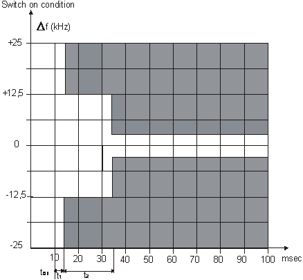
8.10.3 Limits
The results shall be recorded as frequency difference versus time.
During the periods of time t1 and t2, the frequency difference shall not exceed the values given in subclause 8.10.1.
The frequency difference, after the end of t2, shall be within the limit of the frequency error, see subclause 8.1.
During the period of time t3, the frequency difference shall not exceed the values given in subclause 8.10.1.
Before the start of t3, the frequency difference shall be within the limit of the frequency error, see subclause 8.1.
8.11 Conducted spurious emissions conveyed to the antenna
8.11.1 Definition
Conducted spurious emissions are emissions on a frequency or frequencies which are outside the necessary bandwidth and the level of which may be reduced without affecting the corresponding transmission of information. Spurious emissions include harmonic emissions, parasitic emissions, intermodulation products and frequency conversion products, but exclude out of band emissions.
8.11.2 Method of measurement
Conducted spurious emissions shall be measured with the unmodulated transmitter connected to the artificial antenna (see subclause 6.5).
The measurements shall be made over a range from 9 kHz to 2 GHz, excluding the channel on which the transmitter is operating and its adjacent channels.
The measurements for each spurious emission shall be made using a tuned radio measuring instrument or a spectrum analyzer.
8.11.3 Limit
The power of any spurious emission on any discrete frequency shall not exceed 0.25 mW.
|
|

Figure 4: Characteristic of Transmitter’s Transient Frequency
9. Receiver
9.1 Harmonic distortion and rated audio frequency output power
9.1.1 Definition
The harmonic distortion at the receiver output port is defined as the ratio, expressed as a percentage, of the total rms voltage of all the harmonic components of the modulation audio frequency to the total rms voltage of the signal delivered by the receiver.
The rated audio frequency output power is the value stated by the manufacturer to be the maximum power available at the output port, for which all the requirements of this standard are met.
9.1.2 Methods of measurement
Test signals at levels of +60 dBmV and +100 dBmV, at a carrier frequency equal to the nominal frequency of the receiver and modulated by the normal test modulation shall be applied in succession to the receiver antenna port under the conditions specified in subclause 6.2.2.
For each measurement, the receiver's audio frequency volume control shall be set so as to obtain, in a resistive load which simulates the receiver's operating load, the rated audio frequency output power (see subclause 9.1.1). The value of this load shall be stated by the manufacturer.
Under normal test conditions (see subclause 5.3) the test signal shall be modulated successively at 300 Hz, 500 Hz and 1 kHz with a constant modulation index of 3. The harmonic distortion and audio frequency output power shall be measured at all the frequencies specified above.
Under extreme test conditions (subclauses 5.4.1 and 5.4.2 applied simultaneously), the tests shall be made at the receiver's nominal frequency and at the nominal frequency ±1.5 kHz. For these tests, the modulation frequency shall be 1 kHz and the frequency deviation shall be ±3 kHz.
The test shall be carried out on one channel only (see subclause 6.6).
9.1.3 Limits
The rated audio frequency output power shall be at least:
- 200 mW in a loudspeaker;
- 1 mW in the handset earphone if provided.
The harmonic distortion shall not exceed 10%.
9.2 Audio frequency response
9.2.1 Definition
The audio frequency response is the variation in the receiver's audio frequency output level as a function of the modulating frequency of the radio frequency signal with constant deviation applied to its input.
9.2.2 Method of measurement
A test signal of +60 dBmV, at a carrier frequency equal to the nominal frequency of the receiver and modulated with normal test modulation (see subclause 6.4), shall be applied to the receiver antenna port under the conditions specified in subclause 6.2.2.
The receiver's audio frequency power control shall be set so as to produce a power level equal to 50% of the rated output power (see subclause 9.1). This setting shall remain unchanged during the test.
The frequency deviation shall then be reduced to 1 kHz and the audio output is the reference point in figure 5 (1 kHz corresponds to 0 dB).
The frequency deviation shall remain constant while the modulation frequency is varied between 300 Hz and 3 kHz and the output level shall then be measured.
The measurement shall be repeated with a test signal at frequencies 1,5 kHz above and below the nominal frequency of the receiver.
The test shall be carried out on one channel only (see subclause 6.6).
9.2.3 Limits
The audio frequency response shall not deviate by more than +1 dB or -3 dB from a characteristic giving the output level as a function of the audio frequency, decreasing by 6 dB per octave and passing through the measured point at 1 kHz (see figure 5).
|

Figure 5: Audio frequency response
9.3 Maximum usable sensitivity
9.3.1 Definition
The maximum usable sensitivity of the receiver is the minimum level of the signal at the nominal frequency of the receiver which, when applied to the receiver antenna port with normal test modulation (see subclause 5.3), will produce:
- in all cases, an audio frequency output power equal to 50% of the rated output power (see subclause 9.1); and
- a SINAD ratio of 20 dB, measured at the receiver output port through a psophometric telephone filtering network such as described in ITU-T Recommendation P.53 [4].
9.3.2 Method of measurement
A test signal at a carrier frequency equal to the nominal frequency of the receiver, modulated by the normal test modulation (see subclause 6.4) shall be applied to the receiver antenna port. An audio frequency load and a measuring instrument for measuring the SINAD ratio (through a psophometric network as specified in subclause 9.3.1) shall be connected to the receiver output port.
The level of the test signal shall be adjusted until a SINAD ratio of 20 dB is obtained, using the psophometric network and with the receiver's audio frequency power control adjusted to produce 50% of the rated output power. The level of the test signal at the antenna port is the value of the maximum usable sensitivity.
The measurements shall be made under normal test conditions (see subclause 6.4) and under extreme test conditions (subclauses 5.4.1 and 5.4.2 applied simultaneously).
A receiver output power variation of ±3 dB relative to 50% of the rated output power may be allowed for sensitivity measurements under extreme test conditions.
9.3.3 Limits
The maximum usable sensitivity shall not exceed +6 dBmV under normal test conditions and +12 dBmV under extreme test conditions.
9.4 Co-channel rejection
9.4.1 Definition
The co-channel rejection is a measure of the capability of the receiver to receive a wanted modulated signal without exceeding a given degradation due to the presence of an unwanted modulated signal, both signals being at the nominal frequency of the receiver.
9.4.2 Method of measurement
The two input signals shall be connected to the receiver antenna port via a combining network (see subclause 6.2.2). The wanted signal shall have normal test modulation (see subclause 6.4). The unwanted signal shall be modulated by 400 Hz with a deviation of 3 kHz. Both input signals shall be at the nominal frequency of the receiver under test. The measurement shall be repeated for displacements of the unwanted signal of ±3 kHz.
The wanted input signal level shall be set to the value corresponding to the maximum usable sensitivity. The amplitude of the unwanted input signal shall then be adjusted until the SINAD ratio (psophometrically weighted) at the output port of the receiver is reduced to 14 dB.
The co-channel rejection ratio shall be expressed as the ratio in dB of the level of the unwanted signal to the level of the wanted signal at the receiver antenna port for which the specified reduction in SINAD ratio occurs.
The test shall be carried out on one channel only (see subclause 6.6).
9.4.3 Limit
The co-channel rejection ratio, at any frequency of the unwanted signal within the specified range, shall be between -10 dB and 0 dB.
9.5 Adjacent channel selectivity
9.5.1 Definition
The adjacent channel selectivity is a measure of the capability of the receiver to receive a wanted modulated signal without exceeding a given degradation due to the presence of an unwanted modulated signal which differs in frequency from the wanted signal by 25 kHz.
9.5.2 Method of measurement
The two input signals shall be applied to the receiver antenna port via a combining network (see subclause 6.2.2). The wanted signal shall be at the nominal frequency of the receiver and shall have normal test modulation (see subclause 6.4). The unwanted signal shall be modulated by 400 Hz with a deviation of 3 kHz, and shall be at a frequency 25 kHz above that of the wanted signal.
The wanted input signal level shall be set to the value corresponding to the maximum usable sensitivity as measured in subclause 9.3. The amplitude of the unwanted input signal shall then be adjusted until the SINAD ratio at the receiver output port, psophometrically weighted, is reduced to 14 dB. The measurement shall be repeated with an unwanted signal at a frequency 25 kHz below that of the wanted signal.
The adjacent channel selectivity shall be expressed as the lower value of the ratios in dB for the upper and lower adjacent channels of the level of the unwanted signal to the level of the wanted signal.
9.5.3 Limits
The adjacent channel selectivity shall be not less than 70 dB.
9.6 Spurious response rejection
9.6.1 Definition
The spurious response rejection is a measure of the capability of the receiver to discriminate between the wanted modulated signal at the nominal frequency and an unwanted signal at any other frequency at which a response is obtained.
9.6.2 Method of measurement
Two input signals shall be applied to the receiver antenna port via a combining network (see subclause 6.2.2). The wanted signal shall be at the nominal frequency of the receiver and shall be modulated with normal test modulation (see subclause 6.4).
The unwanted signal shall be modulated by 400 Hz with a deviation of 3 kHz.
The wanted input signal level shall be set to the value corresponding to the maximum usable sensitivity as measured in subclause 9.3. The amplitude of the unwanted input signal shall be adjusted to +86 dBmV. The frequency shall then be stepped over the frequency range from 100 kHz to 2 000 MHz in steps not larger than 5 kHz.
At any frequency at which a response is obtained, the input level shall be adjusted until the SINAD ratio psophometrically weighted, is reduced to 14 dB.
The spurious response rejection ratio shall be expressed as the ratio in dB between the unwanted signal and the wanted signal at the receiver antenna port when the specified reduction in the SINAD ratio is obtained.
The test shall be carried out on one channel only (see subclause 6.6).
9.6.3 Limit
At any frequency separated from the nominal frequency of the receiver by more than 25 kHz, the spurious response rejection ratio shall be not less than 70 dB.
9.7 Intermodulation response
9.7.1 Definition
The intermodulation response is a measure of the capability of a receiver to receive a wanted modulated signal without exceeding a given degradation due to the presence of two or more unwanted signals with a specific frequency relationship to the wanted signal frequency.
9.7.2 Method of measurement
Three signal generators, A, B and C shall be connected to the receiver antenna port via a combining network (see subclause 6.2.2). The wanted signal, represented by signal generator A shall be at the nominal frequency of the receiver and shall have normal test modulation (see subclause 6.4). The unwanted signal from signal generator B shall be unmodulated and adjusted to the frequency 50 kHz above the nominal frequency of the receiver. The second unwanted signal from signal generator C shall be modulated by 400 Hz with a deviation of 3 kHz, and adjusted to a frequency 100 kHz above the nominal frequency of the receiver.
The wanted input signal shall be set to a value corresponding to the maximum usable sensitivity as measured in subclause 9.3. The amplitude of the two unwanted signals shall be maintained equal and shall be adjusted until the SINAD ratio at the receiver output port, psophometrically weighted, is reduced to 14 dB. The frequency of signal generator B shall be adjusted to produce the maximum degradation of the SINAD ratio. The level of the two unwanted test signals shall be readjusted to restore the SINAD ratio of 14 dB. The intermodulation response ratio shall be expressed as the ratio in dB between the two unwanted signals and the wanted signal at the receiver antenna port, when the specified reduction in the SINAD ratio is obtained.
The measurement shall be repeated with the unwanted signal from signal generator (B) at a frequency 25 kHz above the wanted signal and with the unwanted signal from signal generator (C) at a frequency 50 kHz above the wanted signal.
The set measurements described above shall be repeated with the unwanted signals below the nominal frequency by the specified amounts.
9.7.3 Limit
The intermodulation response ratio shall be greater than 68 dB.
9.8 Blocking or desensitisation
9.8.1 Definition
Blocking is a change (generally a reduction) in the wanted audio frequency output power of the receiver or a reduction of the SINAD ratio due to an unwanted signal on another frequency.
9.8.2 Method of measurement
Two input signals shall be applied to the receiver via a combining network (see subclause 6.2). The modulated wanted signal shall be at the nominal frequency of the receiver and shall have normal test modulation (see subclause 6.4). Initially the unwanted signal shall be switched off and the wanted signal set to the value corresponding to the measured maximum usable sensitivity (see subclause 9.3).
The audio frequency output power of the wanted signal shall be adjusted, where possible, to 50% of the rated audio frequency output power and in the case of stepped volume controls, to the first step that provides an audio frequency output power of at least 50% of the rated audio frequency output power. The unwanted signal shall be un-modulated at frequencies of ±1 MHz, ±2 MHz, ±5 MHz and ±10 MHz relative to the nominal frequency of the receiver.
The input level of the unwanted signal, at all frequencies in the specified ranges, shall be adjusted so that the unwanted signal causes:
- a reduction of 3 dB in the audio frequency output level of the wanted signal; or
- a reduction to 14 dB of the SINAD ratio (psophometrically weighted) at the receiver audio frequency output, whichever occurs first. This level shall be noted.
9.8.3 Limit
The blocking level for any frequency within the specified ranges, shall be not less than 90 dBmV, except at frequencies on which spurious responses are found (see subclause 9.6).
9.9 Conducted spurious emissions conveyed to the antenna
9.9.1 Definition
Conducted spurious emissions are components at any frequency generated in the receiver and radiated by its antenna.
The level of spurious emissions shall be measured by their power level in a transmission line or antenna.
9.9.2 Method of measurement
Spurious radiations shall be measured as the power level of any discrete signal at the antenna port of the receiver. The receiver antenna port is connected to a spectrum analyzer or selective voltmeter having an input impedance of 50 W and the receiver is switched on.
If the detecting device is not calibrated in terms of power input, the level of any detected components shall be determined by a substitution method using a signal generator.
The measurements shall extend over the frequency range of 9 kHz to 2 GHz.
9.9.3 Limit
The power of any spurious component between 9 kHz and 2 GHz shall not exceed 2 nW.
ANNEX A
(Normative)
ADJACENT CHANNEL POWER MEASUREMENT
This annex describes a method of measurement for adjacent channel power using a power measuring receiver.
The power measuring receiver specifications are given in clause A.2
A.1 Method of measurement
The following procedure shall be used:
a) the transmitter shall be operated at the carrier power determined in subclause 8.2 under normal test conditions. The antenna port of the transmitter shall be linked to the input of the power measuring receiver by a connecting device such that the impedance presented to the transmitter is 50 W and the level at the power measuring receiver input is appropriate;
b) with the transmitter unmodulated, the tuning of the power measuring receiver shall be adjusted so that a maximum response is obtained. This is the 0 dB response point. The power measuring receiver attenuator setting and the reading of the meter shall be recorded.
The measurement may be made with the transmitter modulated with normal test modulation, in which case this fact shall be recorded with the test results;
c) the tuning of the power measuring receiver shall be adjusted away from the carrier so that the power measuring receiver -6 dB response nearest to the transmitter carrier frequency is located at a displacement from the nominal carrier frequency of 17 kHz;
d) the transmitter shall be modulated at 1.25 kHz at a level which is 20 dB higher than that required to produce ± 3 kHz deviation;
e) the power measuring receiver variable attenuator shall be adjusted to obtain the same meter reading as in step (b) or a known relation to it;
f) the ratio of adjacent channel power to carrier power is the difference between the attenuator settings in steps (b) and (e), corrected for any differences in the reading of the meter;
g) the measurement shall be repeated with the power measuring receiver tuned to the other side of the carrier.
A.2 Power measuring receiver specification
The power measuring receiver consists of a mixer, an IF filter, and oscillator, an amplifier, a variable attenuator and an rms value indicator. Instead of the variable attenuator with the rms value indicator it is also possible to use an rms voltmeter calibrated in dB. The technical characteristics of the power measuring receiver are given below.
A.2.1 IF filter
The IF filter shall be within the limits of the following selectivity characteristics (see figure A.1).
Figure A.1
The selectivity characteristic (see table A.1) shall keep the following frequency separations from the nominal centre frequency of the adjacent channel:
Table A.1: Selectivity characteristic
|
Frequency separation of filter curve from nominal centre frequency of adjacent channel (kHz) |
|||
|
D1 |
D2 |
D3 |
D4 |
|
5 |
8.0 |
9.25 |
13.25 |
The attenuation points close to carrier (table A.2) shall not exceed the tolerances shown in table A.2.
Table A.2: Attenuation points close to carrier
|
Tolerance range (kHz) |
|||
|
D1 |
D2 |
D3 |
D4 |
|
+3.1 |
±0.1 |
-1.35 |
-5.35 |
The attenuation points distant from the carrier (table A.3) shall not exceed the tolerances shown in table A.3.
Table A.3: Attenuation points distant from the carrier
|
Tolerance range (kHz) |
|||
|
D1 |
D2 |
D3 |
D4 |
|
±3.5 |
±3.5 |
±3.5 |
+3.5 -7.5 |
The minimum attenuation of the filter outside the 90 dB attenuation points shall be equal to or greater than 90 dB.
A.2.2 Attenuation indicator
The attenuation indicator shall have a minimum range of 80 dB and a reading accuracy of 1 dB. With a view to future regulations an attenuation of 90 dB or more is recommended.
A.2.3 RMS value indicator
The instrument shall accurately indicate non-sinusoidal signals with a crest factor of 10.
A.2.4 Oscillator scope and amplifier
The oscillator scope and the amplifier shall be designed in such a way that the measurement of the adjacent channel power of a low-noise unmodulated transmitter, whose self-noise has a negligible influence on the measurement result, yields a measured value of < -="" 90="">